QubitResonator
λ/4 readout resonator with a coupler section and a mandatory tail to a qubit (legacy Qubit Resonator).
Source: Quantcore. Category: resonator. Module: quantcore_circuits.layouts.others.legacy_resonators.
See also the catalog.
Pins
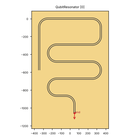
Pin image (default parameters). Light = metal, dark = etched gap, colours = junction layers. A red dot and arrow is a pin and its direction (out of the cell); the red bar is the CPW width a + 2 b. Blue dot = a pin without direction. Units: µm.
pin |
x (µm) |
y (µm) |
direction (°) |
a (µm) |
b (µm) |
purpose |
|---|---|---|---|---|---|---|
|
50 |
-1059.437 |
270 |
10 |
6 |
far end of the line / resonator (see the notes); LOM node |
a, b: CPW centre width and gap where the pin declares them (– = not declared). Position and direction are in the cell’s own frame (at=(0, 0), rot=0).
Notes from the catalog: ‘end’ (tail) is an open end: with ground=True the gap cap lies beyond the port, so anything joined there galvanically is cut off.
Parameters
name |
default |
unit |
description |
|---|---|---|---|
|
|
μm |
Width of center conductor |
|
|
μm |
Width of gap |
|
|
μm |
Turn radius |
|
|
μm |
Meander width (straight run between arcs) |
|
|
μm |
Arc length of a meander turn (radius = arc_length / π) |
|
|
μm |
Neck length |
|
|
μm |
Coupling gap (ground strip around the shorted end) |
|
|
μm |
Coupling length |
|
|
– |
Open far end with a gap cap (False: end left for a connection) |
|
|
– |
Coupling direction |
|
|
– |
Flat coupler (no arc at the coupler start) |
|
|
μm |
Tail connection length |
|
|
μm |
Length of the resonator |
|
|
– |
Points per arc (legacy n) |
|
|
– |
Flip the meander direction |
|
|
– |
Extra tail on the twisted end |
Electrically relevant parameters (sizes, gaps, junction, ports) come first, the rest follows.
LOM model
The cell contributes to the lumped model:
no lumped branches
line |
node |
length (µm) |
a (µm) |
b (µm) |
ends |
|---|---|---|---|---|---|
|
|
3999.993 |
10 |
6 |
short / open |
Nodes: res.
Simulation export notes
C6: eigenmode 50 Ω edge port without a polygon (box edge on a bend / taper / narrow line) (status: fixed; fix in sim_tools/builder.py (straighten_box, edge_port_ok, crossing_square))
C8: GDS polygon with > 4095 points (XY record > 0x8000 bytes) (status: partly fixed; fix in sim_tools/builder.py (FaceMetal.max_points, DesignSimulation.simplified_region, split_large_polygons); sim_tools/geometry_check.py)
How to use
In Python:
from quantcore_circuits.designer import Designer

d = Designer("demo", box=(0, 0, 7500, 7500))
d.add("U1", "QubitResonator", at=(3750, 3750), a=10)   # parameters: see the table above
d.add("PAD", "BondPad", at=(1125, 3750), rot=270)   # a launcher to connect to
d.route("L1", "PAD.a", "U1.end")                # a CPW from the pad to the pin
Pin names go into d.route(...) as INSTANCE.pin, and into snap= / to= when placing. From the shell: qcc components QubitResonator lists the pins; add --schema for the parameters.
In KLayout: Quantcore panel ▸ Components ▸ double-click the cell, then click on the layout to place it. Rotate and mirror before the click; use Connect on two pins to route.
GUI status (kplugin/COMPONENTS_STATUS.md): places ok, edit ok, connect ok, build ok. end port is a capacitive tail, not galvanic: use the hanger for a readout (see README).