SingleXmons (KQC)
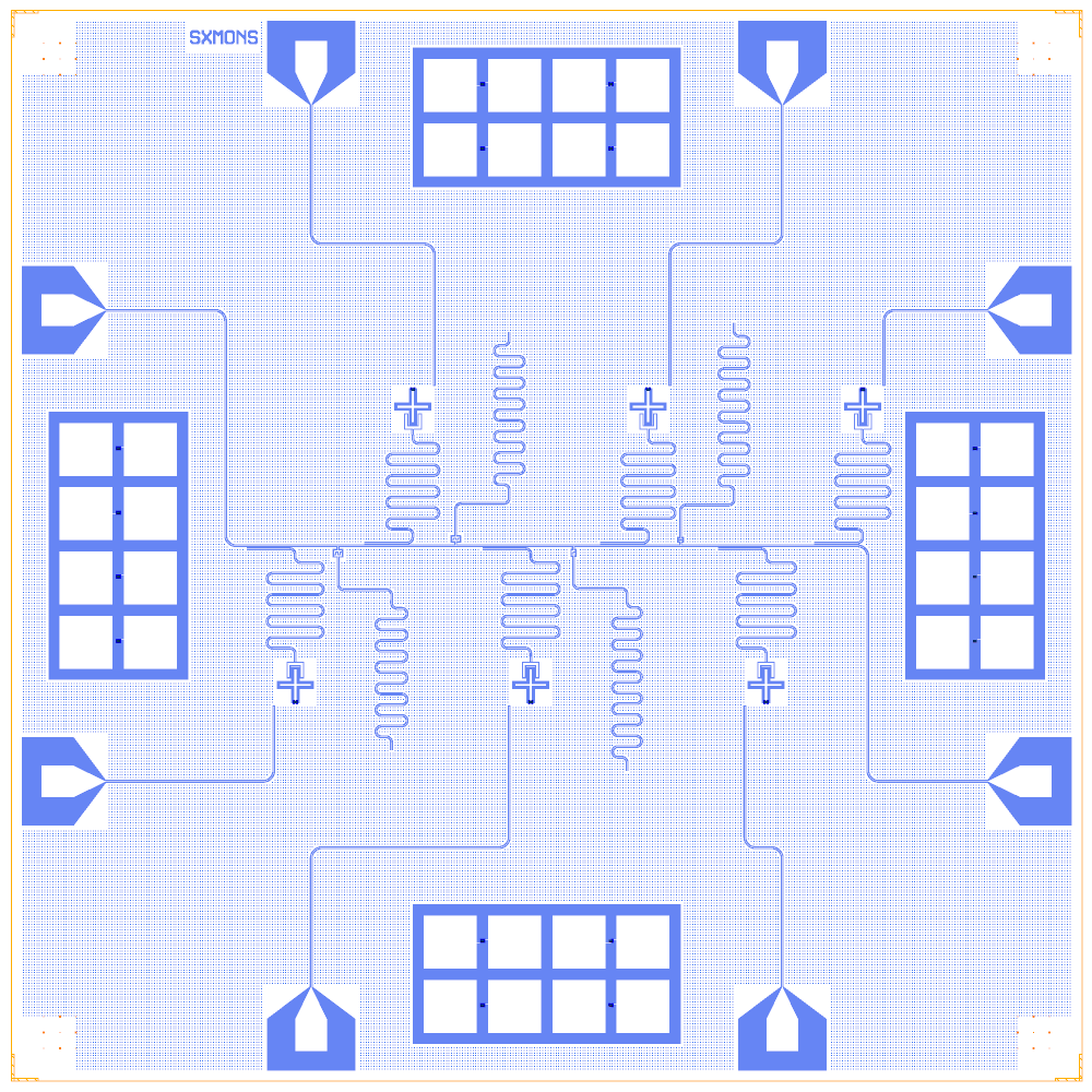
A KQCircuits chip with six fixed-frequency Swissmon qubits on one feedline, each with a quarter-wave readout and its own charge line. Four test resonators and four junction-test arrays share the chip. It is rebuilt on the Quantcore PDK.
Build it to see hanger-style readouts coupled along a feedline, and several qubits sharing one probe line.
At a glance
Notebook |
|
Source |
KQCircuits |
Chip |
10 × 10 mm, SMA8 launchers, chip name “SXMONS” |
On the chip |
6 Swissmons · 6 λ/4 hanger readouts (5000 to 5500 µm) · 1 feedline · 4 test resonators · 6 charge lines · 4 junction-test arrays |
Builds today |
yes (layout built on 2026-11-19 in 10 s) |
How the notebook builds it
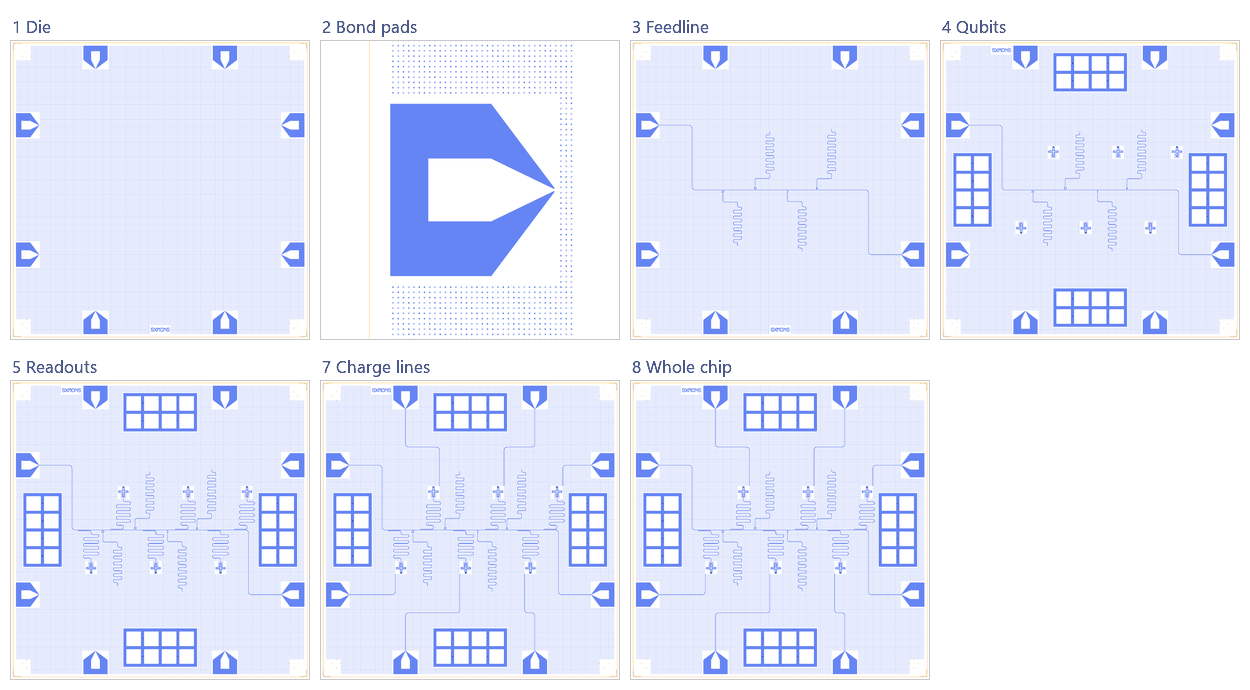
Die. The empty 10 × 10 mm chip with the Quantcore frame (dicing marks, alignment grids, chip boundary, device ID) and the eight launchers.
Bond pads. The launchers moved so their outer etch edge sits 100 µm from the die edge (the pad rule).
Feedline. Tees on the feedline and the test capacitors.
Qubits. Six Swissmons with Quantcore SQUIDs, and the junction-test arrays.
Readouts. Six λ/4 hangers along the feedline.
Charge lines. One per qubit from its launcher.
Whole chip. Sim groups, centring, design saved. (Design 6 has no coupling to add.)
LOM estimates
Numbers are from a run of this notebook on 2026-11-19 (Setup, Design, Check and the LOM cells, 15 s): QuCat normal modes with QuTiP dressed values.
group |
qubit |
f_q (GHz) |
α (MHz) |
resonator |
f_r (GHz) |
κ (MHz) |
χ (MHz) |
|---|---|---|---|---|---|---|---|
QB0+RR0 |
QB0 |
6.542 |
-255 |
RR0 |
5.655 |
0.276 |
-3.92 |
QB1+RR1 |
QB1 |
6.541 |
-256 |
RR1 |
5.556 |
0.263 |
-2.89 |
QB2+RR2 |
QB2 |
6.541 |
-257 |
RR2 |
5.459 |
0.25 |
-2.21 |
QB3+RR3 |
QB3 |
6.54 |
-257 |
RR3 |
5.366 |
0.238 |
-1.74 |
QB4+RR4 |
QB4 |
6.54 |
-258 |
RR4 |
5.276 |
0.227 |
-1.4 |
QB5+RR5 |
QB5 |
6.539 |
-258 |
RR5 |
5.189 |
0.216 |
-1.15 |
test resonator |
length (µm) |
bare f (GHz) |
|---|---|---|
TR0 |
5200 |
6.059 |
TR1 |
5400 |
5.835 |
TR2 |
5600 |
5.627 |
TR3 |
5800 |
5.433 |
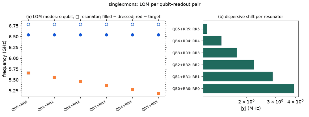
These are lumped-model estimates (component formulas and calibration), not FEM results; see the LOM page for how far to trust them.
Build spec
The rest of this page is the detailed spec the notebook was built from: every component, port, route and length.
Source other-libs/KQCircuits-main/KQCircuits-main/klayout_package/python/kqcircuits/chips/single_xmons.py
(SingleXmons), GPL-3.0 (IQM Finland). Rebuilt from extracted parameters; KQC cells are used through the
registry. What it is: 6 fixed-frequency Swissmons (no flux line; the junction is still the default SQUID), 3 above
and 3 below a horizontal feedline at y = 5000. Each qubit has a λ/4 readout resonator coupled to the feedline over
400 µm, plus a chargeline. Optionally there are 4 test λ/4 resonators, coupled through finger capacitors at T’s in the
feedline. Standard KQC junction-test arrays sit on all 4 sides. 10 × 10 mm, KQC frame = Designer frame. Face
1t1. Checked on 2026-11-02: every length matches KQC.
This is the KQC chip closest to the Quantcore Xmon flow.
Components
instance |
catalog ref |
key params (units) |
at (x, y) |
rot |
notes |
|---|---|---|---|---|---|
QB0, QB1, QB2 |
|
|
(3750,6300), (5950,6300), (7950,6300) |
180 |
above the feedline: cplr1 at (x, 6085) facing down; drive at (x+200, 6500) |
QB3, QB4, QB5 |
|
|
(2650,3700), (4850,3700), (7050,3700) |
0 |
below: cplr1 at (x, 3915) facing up; drive at (x−200, 3500) |
T0–T3 |
|
|
(3050,5000), (4150,5000), (5250,5000), (6250,5000) |
0, 180, 0, 180 |
bottom faces down (T0, T2) or up (T1, T3) |
CT0 |
|
|
snap |
(→ 90) |
interdigital; port a at (3050, 4890.9) |
CT1 |
|
|
snap |
(→ 270) |
a at (4150, 5095.9) |
CT2 |
|
|
snap |
(→ 90) |
a at (5250, 4899.9) |
CT3 |
|
gap type: |
snap |
(→ 270) |
a at (6250, 5081) |
testarray_w/s/e/n |
|
|
(350,3750) / (3750,350) / (8350,3750) / (3750,8350) |
0 |
from |
QP = dict(fluxline_type="none", arm_length=[146]*4, arm_width=[24]*4, gap_width=[24]*4, island_r=2, cpl_length=[0,140,0], cpl_width=[60,24,60], cpl_gap=[110,102,110], cl_offset=[200,200]).
CAP = dict(finger_gap=5, finger_gap_end=5, finger_width=15, ground_padding=10) (from KQC cap_params).
Routes
Feedline (cpw a=10 b=6): FL0 chip.WN → T0.left via (2000,7200), (2000,5000), 4353.16 · FL1 T0.right → T1.right, 1078 · FL2 T1.left → T2.left, 1078 · FL3 T2.right → T3.right, 978 · FL4 T3.left → chip.ES via (8000,5000), (8000,2800), 5053.16.
route |
from → to |
type, length (µm) |
waypoints / hanger |
notes |
|---|---|---|---|---|
RR0 |
QB0.cplr1 → free_end((3250,6027), term=0) |
meander=5000, r=50 |
(3750,5027), (3250,5027), (3250,5127) |
exact KQC: coupling run at y=5027 (27 µm centre spacing, ground_gap 5); meander on the last segment: |
RR1 |
QB1.cplr1 → free_end((5450,6027)) |
5100, r=50 |
(5950,5027), (5450,5027), (5450,5127) |
same pattern |
RR2 |
QB2.cplr1 → free_end((7450,6027)) |
5200, r=50 |
(7950,5027), (7450,5027), (7450,5127) |
|
RR3 |
QB3.cplr1 → free_end((2150,3973)) |
5300, r=50 |
(2650,4973), (2150,4973), (2150,4873) |
below: y = 5000 − 27 |
RR4 |
QB4.cplr1 → free_end((4350,3873)) |
5400, r=50 |
(4850,4973), (4350,4973), (4350,4873) |
|
RR5 |
QB5.cplr1 → free_end((6550,3873)) |
5500, r=50 |
(7050,4973), (6550,4973), (6550,4873) |
|
TR0–TR3 |
CTk.a → free_end(term=0) at (3550,3090.9) / (4650,6995.9) / (5750,2899.9) / (6750,7081) |
meander 5200 / 5400 / 5600 / 5800, r=50 |
from a: (0, ±300), (+500, ±300), (+500, ±400) relative to CTk.a (− for T0, T2) |
meander auto on the last segment |
CL0–CL5 |
chip.NW / NE / EN / WS / SW / SE → QB0…QB5.drive |
cpw |
[(2800,7900),(3950,7900)] / [(7200,7900),(6150,7900)] / [(8150,7200)] / [(2450,2800)] / [(2800,2100),(4650,2100)] / [(7200,2100),(6850,2100)] |
open end at the qubit |
Quantcore hanger variant (recommended for the LOM, tested). Drop T*/CT*/TR* (KQC use_test_resonators=False)
and use one feedline FL = chip.WN → chip.ES via (2000,7200), (2000,5000), (8000,5000), (8000,2800), 12628.3 µm.
Then RRk = d.route(..., q.cplr1, FL.hanger(s=3400 + (x_q − 250 − 2000), length=500, side="left" (QB0–2) or
"right" (QB3–5), ground_gap=5, direction="backward"), meander=L_k, r=50). The s values are 4900, 7100, 9100,
3800, 6000, 8200. The coupler then sits at the shorted end, where KQC has it at about 1.1 mm from the open end, so κ
differs from KQC.
d = Designer("kqc_single_xmons", launchers="SMA8", chip={"name_chip": "SingleXmons"})   # SMA8 default names NW..WN
pos = {0: (3750, 6300, 180), 1: (5950, 6300, 180), 2: (7950, 6300, 180), 3: (2650, 3700, 0), 4: (4850, 3700, 0), 5: (7050, 3700, 0)}
q = {i: d.add(f"QB{i}", "Swissmon", at=(x, y), rot=r, junction=J, **QP) for i, (x, y, r) in pos.items()}
L = [5000, 5100, 5200, 5300, 5400, 5500]
CAPS = [dict(finger_number=4, finger_length=23.1, **CAP), dict(finger_number=4, finger_length=9.9, **CAP),
        dict(finger_number=2, finger_length=14.1, **CAP),
        dict(finger_number=4, finger_length=0, finger_gap=0, finger_gap_end=10, finger_width=10, ground_padding=10)]
for i, x in enumerate([3050, 4150, 5250, 6250]):
    d.add(f"T{i}", "WaveguideCoplanarSplitter", at=(x, 5000), rot=180 * (i % 2), lengths=[11, 11, 31], port_names=["right", "left", "bottom"])
    d.add(f"CT{i}", "FingerCapacitorSquare", snap="b", to=f"T{i}.bottom", **CAPS[i])
# feedline FL0..FL4 as listed; then readout (exact KQC):
for i, (x, y, r) in pos.items():
    f = 1 if i < 3 else -1; yc = 5000 + 27 * f; w = 900 if i < 4 else 1000
    d.route(f"RR{i}", q[i].cplr1, Designer.free_end(at=(x - 500, yc + f * (100 + w)), term=0), meander=L[i], r=50,
            nodes=[(x, yc), (x - 500, yc), (x - 500, yc + 100 * f)]).set(meander_segment=5)
Launchers, pads, test structures, markers, labels
SMA8 (all 8 used): WN (800,7200) feedline in, ES (9200,2800) feedline out; NW (2800,9200), NE (7200,9200), EN (9200,7200), WS (800,2800), SW (2800,800), SE (7200,800) are chargelines CL0–CL5. There are 4 junction-test arrays.
LOM node structure (qubit ↔ resonator ↔ feedline ↔ bus ↔ control lines)
QB0–QB5: island + SQUID + one coupler node cplr1. cplr0 and cplr2 are absent because
cpl_length=0.Hanger variant (tested): RRk is a λ/4 TLres at QBk.cplr1 and K_RRk a HANGER to node FL. The lumped values are f = 6.40 / 6.28 / 6.15 / 6.04 / 5.93 / 5.82 GHz and κ ≈ 0.44 → 0.33 MHz. The chip ports WN/ES are 50 Ω.
Exact variant: RRk is a λ/4 at cplr1, but its coupling to the feedline is not in the LOM. The free end does not hang off the feedline, so add
d.couple("K_RR0", "QB0.cplr1", ...)or use a C-matrix. TRk is a λ/4 at CTk.a, with CTk as series C to the T node and the feedline as one conductor through all T’s.CLk:
drivecontrols (no flux controls).
Targets (if stated)
None. readout_res_lengths=[5000,5100,5200,5300,5400,5500], test_res_lengths=[5200,5400,5600,5800],
n_fingers=[4,4,2,4], l_fingers=[23.1,9.9,14.1,10], type_coupler=[interdigital×3, gap].
Simplifications for a first rebuild
Build the hanger variant first: it needs no test resonators or junction tests and gives the full Quantcore LOM. Then
add the exact variant for geometry parity. KQC sets meanders=8/9 (and 13–15 for the test resonators) in its
meanders. Ours are auto-sized, so the meander widths differ while the total lengths match.
Quantcore PDK rebuild
The notebook is a Quantcore-PDK rebuild of the source chip. The netlist, LOM and imported components are kept, and the process is Quantcore’s.
Notebook: examples/designs/kqc/singlexmons.ipynb.
Chip: the Quantcore die frame (L dicing markers 1000/0, 3 × 3 alignment grids 1001/0, chip boundary 100/0, device ID where an edge is free; any brand text is QCT), drawn on the source’s 10 × 10 mm chip (its launchers sit on the chip edges, so the design does not fit the 7.5 mm die). KQC’s ChipFrame (dicing edge, corner markers, labels) is not drawn. KQC’s original grids its whole ground plane (
with_grid, 5 µm squares on a 10 µm step). The rebuild keeps that coverage at the PDK density instead (chip parametercheese: "chip",with_grid: false): 5 µm squares with 20 µm gaps over the whole die, at least 4 µm from the 3/0 keep-outs, inside the design area and clear of the frame markers and the device ID.Stack: sapphire 650 µm, εr 10.25 (the PDK default stack, used by the LOM estimates and every FEM export); KQC’s own simulation default is silicon (εr 11.45), so LOM capacitances and resonator frequencies here are for sapphire.
Junctions: Quantcore Nb/AlOx/Nb trilayer junctions (
junction_typefromlayouts.registry.trilayer_junction): fingers on 2/0 + 4/0, spacer 50/0 with the 51–53/0 gradient, sized on the PDK junction rule (Nb Δ = 1.4 meV, I_c·R_n = πΔ/2e, R_n·A 13.5 kΩ·µm² and C_J 50 fF/µm² assumed); every Swissmon’s SQUID becomes a PDK SQUID of two 0.25 × 0.6 µm junctions → R_n = 45 kΩ in parallel, L_J = 6.73 nH at zero flux, C_J = 15 fF (in the 40–50 kΩ window). KQC’sjunction_widthsets the straight finger. This replaces the assumed Lj 16 nH + 2 fF. Expected f_q ≈ 6.5 GHz (was 4.49 GHz), now above the ≈ 5.6–6 GHz readouts (estimate from the pre-rebuild LOM C_Σ). The fourJunctionTestPadsarrays get the same Quantcore SQUID.Kept: the topology and every KQC element with the source’s parameters, positions and orientations, the launcher assignment, every route’s path and length, the sim groups (readouts 5000–5500 µm with their 27 µm coupling, the test resonators, the junction-test arrays).