Flux-tunable qubit chip (chip_05)
A 7.5 mm die with seven Xmon qubits and eight quarter-wave resonators on one feedline. Two of the qubits (Q4 and Q5)
have a SQUID instead of a single junction and a flux line from a small pad at the top or bottom edge, so their
frequency can be tuned with a current. The chip also has flux-trap hole arrays, two HSQ junction test pads and HSQ
corner markers. It is Quantcore’s own chip from the QWri legacy script chip_05_flux_TLQubits.py (May 2024), the one
that tests flux tuning.
The rebuild draws it from Quantcore PDK parts: the flux lines are routed with the PDK router and the resonator tails run into the claws. The PDK cheese (5 µm squares with 20 µm gaps, at least 4 µm from the 3/0 keep-outs) also covers the whole die, and the holes drawn in the original layout stay. Build this one to see flux lines and SQUID qubits next to a readout feedline.
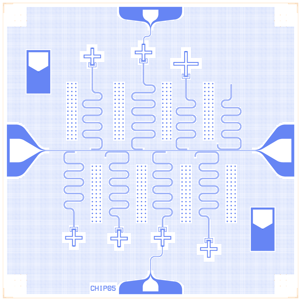
chip_05_flux_tlqubits as rebuilt on the Quantcore PDK
At a glance
Notebook |
|
Source script |
|
Chip |
7.5 × 7.5 mm die, 10/6 µm CPW |
On the chip |
7 Xmons (Q4, Q5 SQUIDs) · 8 λ/4 resonators · 2 flux lines (4/6 µm) · 8 hole arrays · 2 HSQ test pads · 4 HSQ corner markers |
Builds today |
yes, rebuilt from its JSON on 2026-11-19 in 2.5 s (the notebook itself was not re-run) |
Pictures
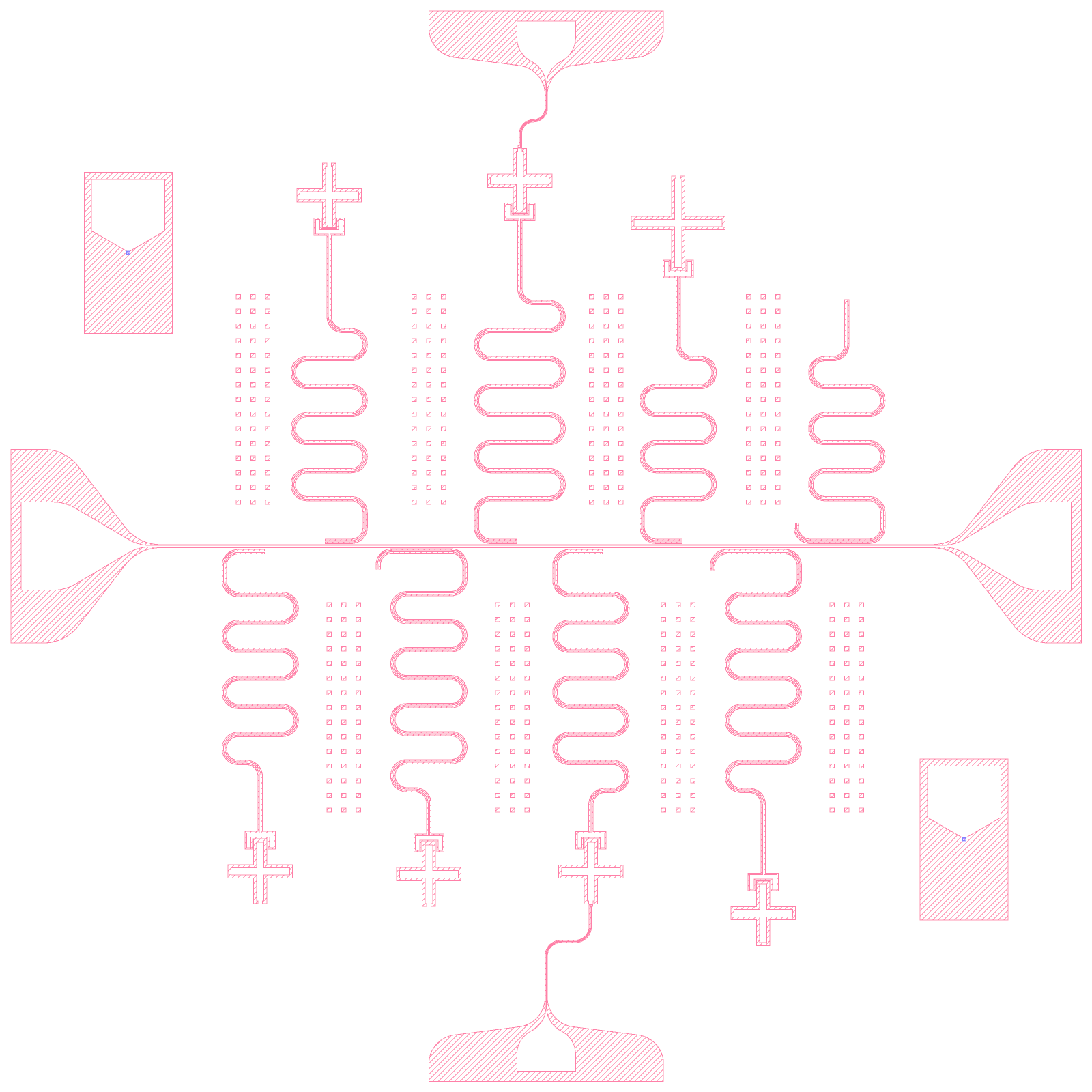
chip_05_flux_tlqubits: the original legacy layout (render of the legacy GDS)
chip_05_flux_tlqubits: the Quantcore rebuild
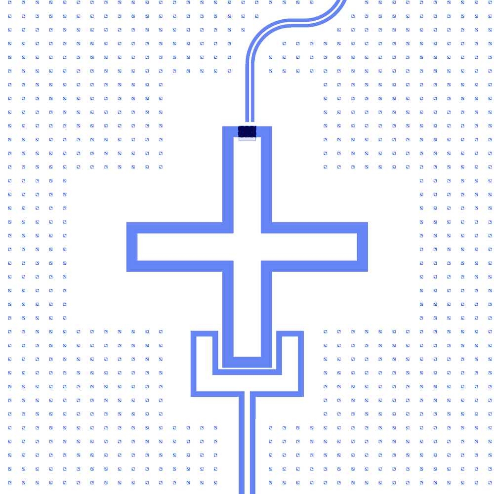
Q4, a qubit with a flux line: the line arrives at the top, the resonator tail at the claw
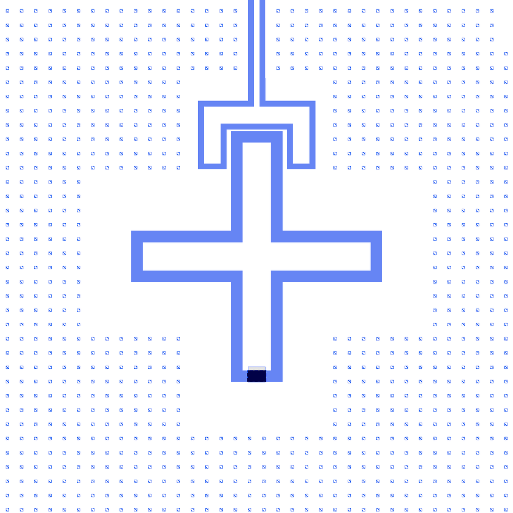
Q1, a single-junction qubit, for comparison
An HSQ junction test pad
LOM estimates
The notebook’s saved outputs hold no LOM run (its LOM cells were not executed), so there are no estimates to show here and none were computed for this page.
Build spec
The rest of this page is the detailed spec the notebook was built from: components, positions, parameters and what changed from the legacy script.
Source: components/python/chip_05_flux_TLQubits.py (create_test_chip(), May 2024; writes
chip_05_flux_TLQubits_1.0.gds). Legacy QWri library, Quantcore internal. Notebook
examples/designs/legacy/chip_05_flux_tlqubits.ipynb.
Changes made in the rebuild
Junction indexing fixed:
bot[i](Q1–Q5 js 5, Q6 js 8); the junction-layer reference uses the same sizes.Flux-line corners: the largest radius that fits each line. FLUX4 r = 75 µm (its 155 µm pad lead cannot hold 100), FLUX5 the legacy 100 µm; no break or overlap (checked in a render).
R8: the PCell’s own open end (
ground=True, as chip_10a does) instead of theresonatorGndbox: CUT8 andW_R8removed.Device ID:
CHIP05kept, placed by the frame rule.claw_tail_gap= 10 µm (legacycap_spacing).Junctions: legacy HSQ cells at the legacy fingers on the PDK junction rule (Nb trilayer, Δ = 1.4 meV, I_c·R_n = πΔ/2e = 2.20 mV, R_n 40–50 kΩ, qubits 4–8 GHz; PDK process
get_pdk().junction: R_n·A 13.5 kΩ·µm², C_J 50 fF/µm², both assumed by the PDK): Q1–Q3 45 kΩ, Q6 28 kΩ, SQUIDs 22.5 kΩ parallel. LOM: f_q 5.8–6.1 GHz (SQUIDs 7.8 at zero flux); Q1/R1 and Q2/R2 hybridised.The notebook’s JSON was rebuilt from its layout cell. The notebook has not been re-run, so its outputs are cleared and its PNGs may be out of date.
What it is: a 7.5 × 7.5 mm die centred on (0, 0) → Designer (x + 3750, y + 3750); PDK v2 die frame replaces the
base-metal corner Markers and the layer-10 outline; the HSQ corner markers are kept. Feedline + two rounded pads
(as chip_03), eight Coupled Resonators (ground=False: tails without an end cap, joining the claws), seven Xmons
(Q4, Q5 SQUIDs with flux lines from two small pads at the top/bottom edge centres), flux-trap holes, two HSQ test
pads, labels “500nm”, “800nm”, “QCG_Nb05_W”.
Builds: yes. Not reproduced: labels, the legacy flux-line end geometry (thin 1 µm section + ground
boxes). Junction windows (CLEARER) as Xmon.junction_window; junctions from junction_creator_HSQ /
squid_creator_HSQ (the scripts the source imports) as TrilayerJunctionHSQ / TrilayerSquidHSQ, XOR 0 on the
junction layers.
Components (legacy frame, µm)
instance |
legacy → catalog ref |
params |
at |
rot / mirror |
|---|---|---|---|---|
FL |
Coplanar Waveguide → |
5460 → 5360 (pads snapped, same etch), a/b 10/6 |
(0, 0) |
0 |
PL, PR |
Connector Pad → |
600 × 200, taper 500, 10/6, round, sim False |
(∓2680, 0) |
270° / 90° |
PFT, PFB |
Connector Pad ( |
400 × 150, taper 100, trace 4/6, round |
(0, ±3155) |
180°; PFB mirrored |
R1 … R8 |
Coupled Resonator → |
common gap 10, clength 200, cgap 7, width 300, neck 400, ground False; cpw_len 4740 / 4920 / 5590 / 6200 / 5200 / 4250 / 5840 / 4500; flip R2, R3, R7, R8; clength 400 (R3, R7, R8), 250 (R5); width 400 (R4) |
x = −2000, −1430, −850, −280, 280, 850, 1430, 2000; y = −38, 33, −33, 33, −38, 33, −38, 33 |
mirror True at +33 |
Q1 … Q7 |
Xmon Cross → |
as chip_03 (width 400; Q6 600) |
(−1950, −2218), (−1480, 2391), (−800, −2237), (−180, 2492), (305, −2219), (900, 2203), (1480, −2503) |
0° / 180° alternating |
junctions |
|
as built ( |
(x, y ± 210) (Q6 ± 310) |
|
CLEARER |
30 × 27 µm boxes cut from 1/0 and 3/0 at (x, y ± 207) (Q6 ± 307): from 6.5 µm inside the arm to 0.5 µm into the ground |
|
||
FLUX4, FLUX5 |
raw path polygons (4 µm centre, 6 µm gaps, corners rounded at 100 µm) + 50 µm thin tip (1 µm) + ground boxes |
Designer routes |
||
H0 … H7 |
|
|
(x − 50, y): x = −2050, −1430, −850, −280, 360, 850, 1430, 2000; y = 300 / −1800 alternating |
0 |
CUT8 |
|
|
(2045, 1660) |
90° |
TP1, TP2 |
|
|
(−2850, 2000), (2850, −2000) |
0 |
HSQ0 … HSQ3 |
|
|
corners |
1/2/3/0 |
Resonator tail ↔ claw
Tails without end caps run 0.9 / 2.9 / 17.9 / 22.9 / 0.9 / 29.9 / 6.9 µm into the claw tails of Q1 … Q7: the strip and
the claw are one conductor (checked on the rebuilt metal). LOM: d.couple("W_Qi", "Qi.claw_n", "Ri.end", wire=True).
LOM node structure
FL.line (50 Ω at each pad) ─ HANGER (K_Ri) ─ Ri.res (λ/4, shorted at the coupler) = Qi.claw_n ─ C_g ─ Qi
island (C, JJ or SQUID to ground; Q7 no junction). FLUX4/FLUX5 → control:flux of Q4/Q5. R8: the uncapped tail
would run into the ground (λ/2), but CUT8 opens it, so R8 is an open λ/4 (W_R8 → the CUT8 termination): 7.085 GHz
bare, 7.048 GHz on the feedline (target 7.0). A simulation selection of R8 must include CUT8.
Targets
Source comments: R1 6.5, R2 6.25, R3 5.5, R4 5, R5 6, R6 7.2, R7 5.25, R8 7 GHz.
Keep-outs / frame
Pads sit at all four edge centres, so the frame’s device ID (CHIP05) slides along the bottom edge to the first
free spot, (4600, 100)–(5300, 400), clear of PFB. HSQ markers in the corner marker areas (legacy positions kept).