MQT DASQA mapper
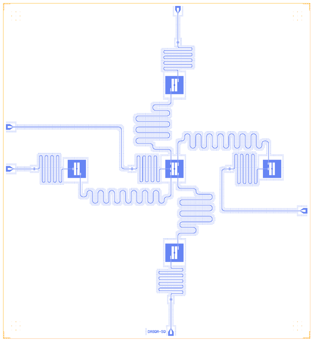
MQT DASQA (Munich Quantum Toolkit, MIT, © 2023 Jagatheesan Jack) turns a quantum circuit into a chip layout: the circuit’s qubit-connectivity profile gives a square-lattice placement and qubit frequencies chosen for yield, and a mapper draws the result as a Qiskit Metal design. The example in its README has five pocket transmons in a plus, the centre qubit joined to each neighbour by a meandered bus, and every qubit read out through an interdigital series capacitor to its own launchpad. The notebook rebuilds that example on the Quantcore PDK (GPL-3.0): an 11 × 12 mm die with the Quantcore frame, sapphire, trilayer junctions and the five launchpads on the 100 µm pad rule.
The generator leaves the readout lengths and the neighbours’ frequencies to steps that are not run here (a Monte-Carlo yield search and an empty resonator optimiser), so this rebuild sets them: qubits at 5.04 to 5.30 GHz around the generator’s 5.17 GHz centre qubit, readouts at 6.6 to 7.4 GHz. The buses are this rebuild’s choice too: dispersive λ/2 lines at 5.85 to 6.30 GHz. The generator’s own bus rule, λ/2 at a qubit’s frequency on silicon, would put them on the qubits on this sapphire stack, where they hybridise with them.
At a glance
Notebook |
|
Source |
|
Chip |
11 × 12 mm Quantcore die, the source’s 3.5 × 3.0 mm qubit grid centred in it, CPW 10 / 6 µm |
On the chip |
5 launchpads · 5 pocket transmons ( |
Builds today |
yes (layout built on 2026-11-19 in 10 s) |
How the notebook builds it
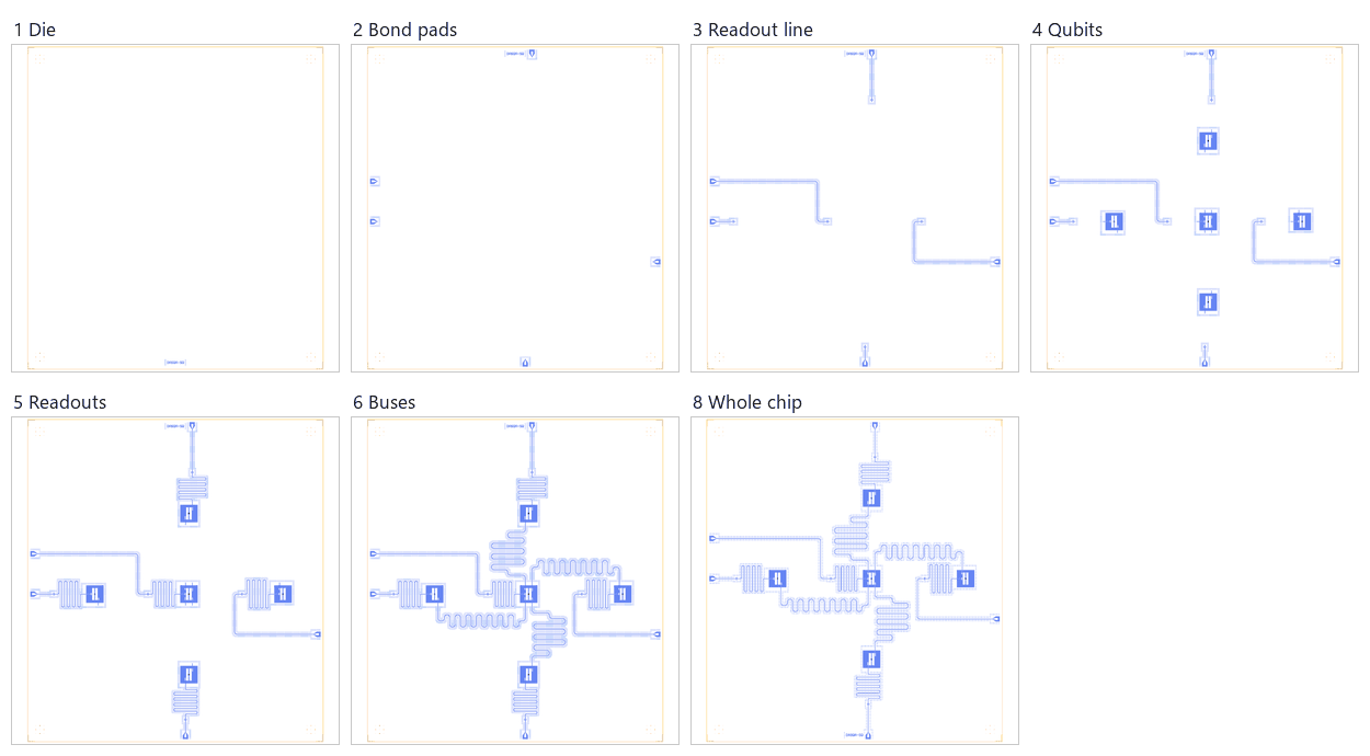
Die. The 11 × 12 mm die with the frame and the device ID
DASQA-5Q. Source positions map onto it as source + (2500, 2500) µm.Bond pads. Five launchpads on the 100 µm pad rule. Three keep their place along the edge; the pads of
Q_4andQ_0, which the mapper puts inside the plus, move to the west and east edges.Readout line. The five
CapNInterdigitalseries capacitors at the mapper’s positions and their lines to the pads.Qubits. Five
TransmonPocket6pockets on the mapper’s grid with its connection pads, each with a trilayer junction sized for its frequency (L_J 12.5 to 15.3 nH).Readouts. Five λ/2 meanders, one between each qubit’s readout pad and its capacitor, at 6.6 to 7.4 GHz.
Coupling. Four dispersive buses from
Q_4to its neighbours at 5.85 to 6.30 GHz, 9.44 to 10.24 mm long (this rebuild’s choice; the generator’s rule gives 11.28 to 11.57 mm).Control lines. None: the generator draws no drive or flux lines.
Whole chip. One sim group per qubit with its readout, the targets, the centring of the core (+135.5, +573 µm) and the save.
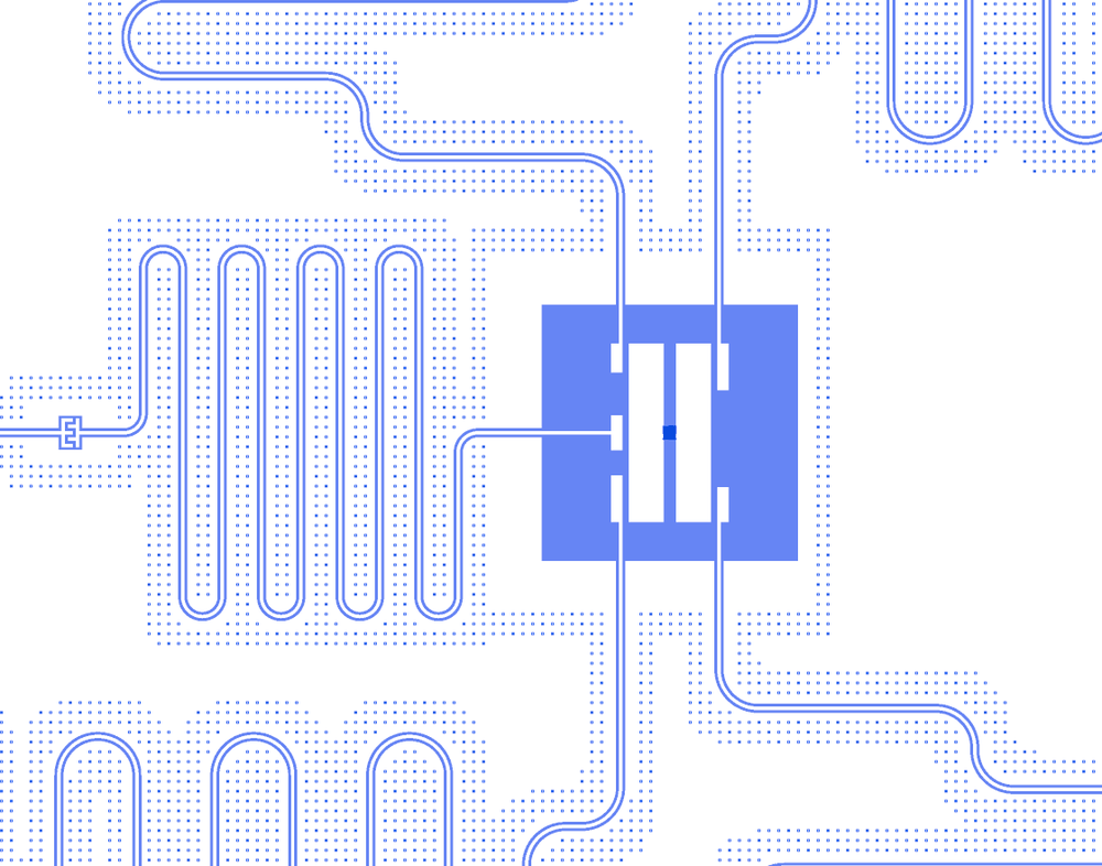
The centre of the plus: Q_4 with its five connection pads, the leads of the four buses, its readout meander and
series capacitor, and the start of its line to the west edge.
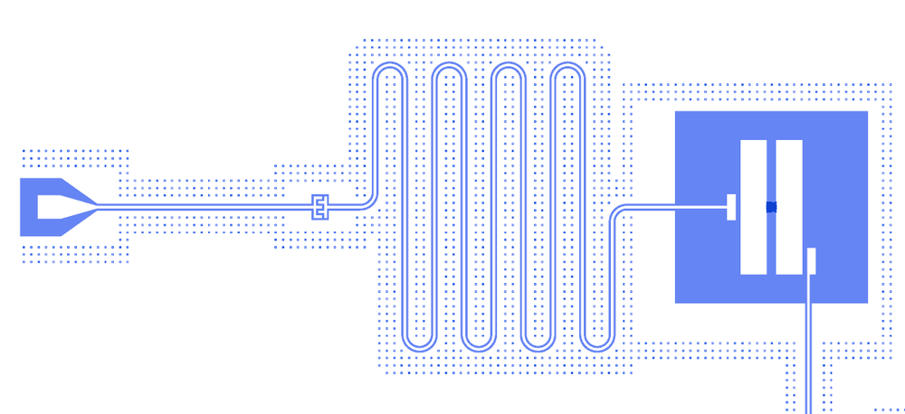
The readout chain of Q_3: the launchpad at the west edge, its line, the CapNInterdigital, the 8.3 mm λ/2 meander
and the pocket’s B4 pad.
LOM estimates
Numbers are from a run of this notebook on 2026-11-19 (Setup, Design, Check and the LOM cells, 42 s): QuCat normal modes with QuTiP dressed values. The rebuild’s plan is in brackets.
group |
qubit |
f_q (GHz) |
α (MHz) |
resonator |
f_r (GHz) |
κ (MHz) |
χ (MHz) |
|---|---|---|---|---|---|---|---|
Q_0R |
Q_0 |
5.025 (5.04) |
-409 |
Readout_0 |
6.616 (6.6) |
0.527 |
-1.12 |
Q_1R |
Q_1 |
5.105 (5.10) |
-375 |
Readout_1 |
6.785 (6.8) |
0.565 |
-2.73 |
Q_2R |
Q_2 |
5.206 (5.24) |
-371 |
Readout_2 |
6.974 (7.0) |
0.612 |
-2.66 |
Q_3R |
Q_3 |
5.295 (5.30) |
-387 |
Readout_3 |
7.189 (7.2) |
0.673 |
-1.45 |
Q_4R |
Q_4 |
5.148 (5.17) |
-327 |
Readout_4 |
7.375 (7.4) |
0.726 |
-0.766 |
Each bus with the two qubits it joins: the bus’s QuCat normal mode and its participation, the bus-mediated exchange
coupling J (from the avoided crossing, exchange_coupling) and the static ZZ (QuTiP).
bus |
length (µm) |
bus mode (GHz) |
bus participation |
J (MHz) |
static ZZ (kHz) |
|---|---|---|---|---|---|
CS_3_4 (Q_3–Q_4) |
9442.6 |
6.300 (6.30) |
0.98 |
4.30 |
+97.2 |
CU_2_4 (Q_2–Q_4) |
9697.5 |
6.150 (6.15) |
0.97 |
4.84 |
+120.8 |
CU_4_1 (Q_4–Q_1) |
9969.3 |
6.000 (6.00) |
0.97 |
3.46 |
+104.1 |
CS_4_0 (Q_4–Q_0) |
10244.3 |
5.850 (5.85) |
0.95 |
3.47 |
+120.5 |
The bus frequencies are this rebuild’s dispersive choice: each bus sits 0.55 to 1.25 GHz above the qubits it joins,
316 MHz or more below the lowest readout and 150 MHz from the next bus, since all four meet at Q_4. In the CU_4_1
and CS_4_0 groups the linear modes of the two qubits lie within 20 MHz of each other and mix by 12 to 18 %, but their
dressed f_q are 43 and 123 MHz apart and QuTiP does not flag them as hybridised.
The generator makes each bus λ/2 at a qubit’s own frequency on silicon (11283 to 11566 µm). On sapphire, loaded by the
connection pads, those lengths come out at 5.16 to 5.27 GHz, on the qubits. The notebook’s LOM 3 cell puts CS_3_4
back on the generator’s 11283 µm in a copy: the bus mode falls from 6.300 to 5.270 GHz, its own participation drops
from 0.98 to 0.83 with 0.15 of Q_4’s junction in it, and the Q_3–Q_4 static ZZ goes from +97 kHz to -10.8 MHz.
LOM 3 is not part of the timed run; these numbers come from the same code run on the saved design.
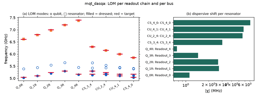
These are lumped-model estimates from component formulas and calibration; no FEM job has been solved. The LOM page says how far to trust them.
Build spec
The rest of this page is the spec the notebook was built from: the generator’s rules, the example it ships, and what the rebuild sets or changes.
Source: cda-tum/mqt-dasqa (arXiv:2305.07052) · licence MIT (© 2023 Jagatheesan
Jack, checked in LICENSE). Read, never run: README, config.yml, the mapper code
(src/mapper/qubit/metal/transmon_pocket_6_qubit.py, capacitor/metal/capacitor.py, launchpad/metal/launchpad.py,
qubit_connector/metal/route_meander_connector.py, qubit_capacitor_connector/metal/qubit_capacitor_connector.py,
capacitor_launchpad_connector/metal/capacitor_launchpad_connector.py), the frequency generator
(src/architecture_generator1/frequency/frequency.py, yieldsimulator/yieldsimulator.py), the optimiser
(src/optimizer/metal/optimizer.py) and the example image docs/images/4_qubit_2D_square_lattice.png.
There is no stored layout or GDS: the output is a live Metal design.
What it is: a generator. A QASM circuit gives a qubit-connectivity profile, which gives a square-lattice placement
with yield-optimised frequencies, which is mapped to Metal: TransmonPocket6 qubits, RouteMeander buses, and per
qubit an interdigital CapNInterdigital readout capacitor with lines to the qubit and to a LaunchpadWirebond. The
shipped image (titled “4 qubit 2D square lattice”) shows 5 qubits in a plus: Q_4 in the centre with Q_0 (east),
Q_1 (north), Q_2 (south) and Q_3 (west) around it.
Generator rules (source frame, µm)
Qubits. The qubit at grid (x, y) is placed at (3500·x, 3000·y), orientation −90. Connection pads B0 (−1, −1, 75 µm), B1 (−1, +1, 120), B2 (+1, −1, 120), B3 (+1, +1, 90), plus B4 (0, −1, 90) on inner rows. Unused pads are removed. Every other pocket option is Metal’s default.
Frequencies. The centre qubit gets the middle of the 5.00–5.34 GHz band (5.17 GHz); the others are placed one by one by a Monte-Carlo yield search (σ 30 MHz, 10⁵ trials, collision rules with α = −340 MHz). The optimiser then tunes each pocket’s
pad_gapandpad_heightfor f_q with pickled regression models.config.ymlalso sets E_C/E_J = 50 for every qubit, which no model uses.Buses.
RouteMeander, fillet 99 µm, length λ_g/2 at the frequency of the pair’s first qubit from Metal’sguided_wavelength(10/6 µm CPW, 750 µm silicon, εr 11.9, 200 nm film). Sideways buses (CS_a_b) have leads of 0.3 and 0.4 mm and an asymmetry of −200 µm; upward ones (CU_a_b) leads of 0.5 and 0.25 mm and an asymmetry of ±700 µm.Readouts. A
RoutePathfinderfrom a qubit pad to the capacitor through one anchor (leads 200 µm, fillet 90 µm), with no length. The optimiser’s resonator step is empty.Capacitors and launchpads. Fixed offsets from the qubit: on the bottom and top rows 150 µm off its axis in x and 1600 µm (capacitor, orientation 0) or 2000 µm (launchpad) beyond it in y; on the middle row 1450 µm (capacitor, orientation −90) and 1750 µm (launchpad) west of it. On this plus that puts
Q_4’s andQ_0’s launchpads inside the chip.
Frame (example): qubits at (0, 3), (3.5, 0), (3.5, 3), (3.5, 6), (7, 3) mm, launchpads up to 2 mm outside the plus. Box (0, 0, 11000, 12000), Designer = source + (2500, 2500), then the core is centred in the die.
Components and routes (example)
item |
catalog ref |
in the rebuild |
|---|---|---|
Q_0 … Q_4 |
|
Metal’s pocket defaults (pads 455 × 90 µm, gap 30 µm, pocket 650 µm) and the mapper’s connection pads; a trilayer junction sized for f_q 5.04 / 5.10 / 5.24 / 5.30 / 5.17 GHz (this rebuild’s plan) |
CS_3_4, CU_2_4, CU_4_1, CS_4_0 |
bus meanders centre ↔ neighbour |
this rebuild’s choice: dispersive λ/2 at 6.30 / 6.15 / 6.00 / 5.85 GHz, 9442.6 / 9697.5 / 9969.3 / 10244.3 µm (v_ph / 2f with a 0.944–0.951 pad-loading factor from the LOM), r 99 µm, on waypoints set like the source’s leads and asymmetry; the generator’s rule gives 11282.6 / 11411.8 / 11566.3 / 11566.3 µm |
Cap_Readout_0 … 4 |
|
Metal’s defaults at the mapper’s positions; the north and south ones 25 µm closer to the qubit’s pin axis |
Readout_0 … 4 |
λ/2 meander between the qubit pad and the capacitor |
this rebuild’s choice: 9089.8 / 8822.4 / 8570.3 / 8332.3 / 8107.1 µm for 6.6 / 6.8 / 7.0 / 7.2 / 7.4 GHz, r 50 µm |
TL_Readout_k, Launch_Readout_k |
route, |
pads on the 100 µm rule; |
LOM node structure
A star: Q_4 bus-coupled to its four neighbours, each bus a λ/2 TLres between two corner pads. Each qubit has a λ/2
readout from its pad to a series IDC and on to its own launcher port; there is no shared feedline.
Rebuild (Quantcore PDK)
Frame and stack: the Quantcore frame on the 11 × 12 mm die, device ID
DASQA-5Q; sapphire 650 µm, εr 10.25.Junctions: Quantcore trilayer junctions sized with
size_junctionfor the plan on this design’s LOM C_Σ (57.5 to 69.1 fF with C_J): L_J 15.31 / 14.03 / 13.47 / 13.47 / 12.47 nH for Q_0 … Q_4. R_n is 83 to 102 kΩ, outside the 40–50 kΩ window, so the DRC flagspdk_rn; the plan is kept.Buses: dispersive at 5.85 to 6.30 GHz, 150 MHz apart, between the qubits and the readouts, in place of the generator’s λ/2 at the qubit frequency (which lands on the qubits on sapphire).
Pads: all five launchpads 100 µm from the die edge.
Cheese: the PDK band, since the source exports no GDS and has no cheese of its own.
DRC: 0 errors, 10
dangling_portwarnings (the junction attachment pointssquid_a/squid_b), 5pdk_rn.FEM: five sim groups
Q_kR(qubit, readout meander, capacitor; 50 µm margins). The notebook exports their Q3D jobs and theQ_3Reigenmode and driven jobs; none is solved.
What the rebuild does not reproduce
The yield search and the regression models are not run, so the neighbours’ frequencies are a hand-picked plan inside the generator’s band, clear of its collision rules, and the pockets keep Metal’s default geometry.
The readout lines become λ/2 meanders with set frequencies; in the source they have no length or frequency.
The buses are shorter than the generator’s estimate: dispersive at 5.85 to 6.30 GHz on sapphire, where the source’s λ/2 at the qubit frequency on silicon would sit on the qubits. They use the source’s pins, leads and asymmetry, but their meander shapes come from the qcc router, not from Metal’s
RouteMeander.The value of the generator is its flow, placement on a 3.5 × 3.0 mm grid from a circuit profile, which this page covers for one shipped example only. A Quantcore analogue is
lom.synthesizedrivingDesigner.array.