The flow
Quantcore circuits turns a chip idea into a layout, checks it, simulates it and feeds the numbers back into the
design, with one file, design.json, throughout. This page lists the steps, the three ways to start, the files each
step writes and the qcc command for each step.
The loop
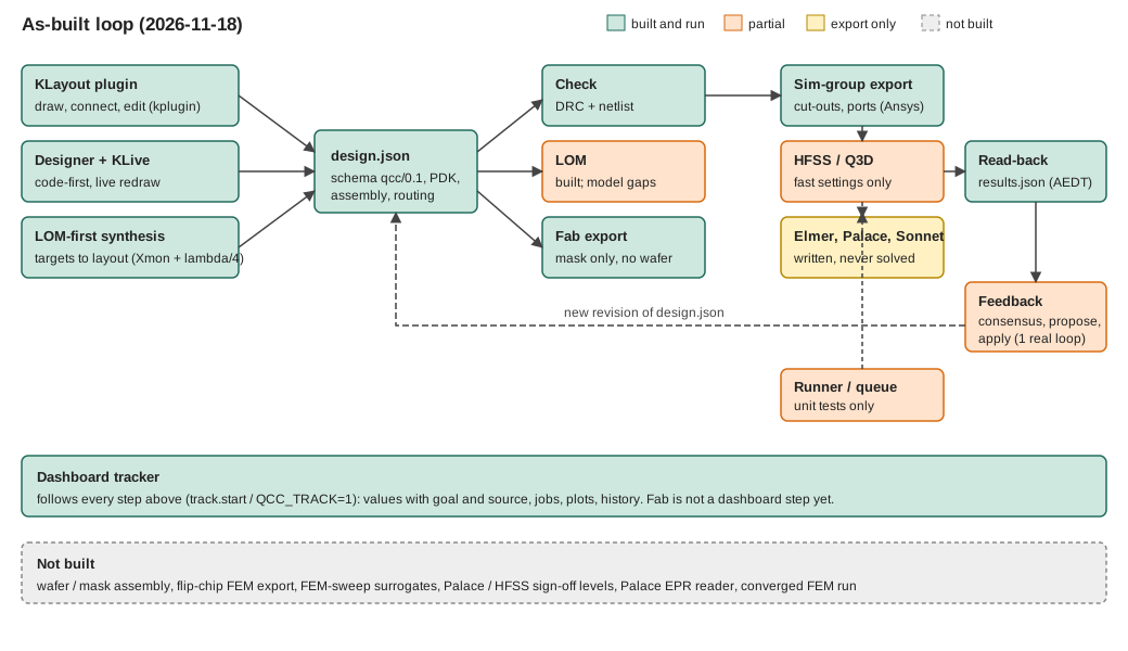
The loop as built. Green: built and run for real. Orange: built, part of it unverified. Yellow: solver input is written but was never solved. Grey: not built.
Step |
What happens |
Page |
|---|---|---|
Draw |
Place components, connect pins, route lines. Three ways: the KLayout plugin, the Python |
|
Process rules |
One PDK: stack, die frame, 100 µm pad rule, keep-outs, cheese, junction process |
|
Build and check |
|
|
LOM |
The layout becomes a lumped circuit; QuCat and QuTiP give f_q, alpha, f_r, chi, kappa, g |
|
Simulate |
A sim group is cut out of the chip and written as an HFSS / Q3D job (also Elmer, Palace, Sonnet input) |
|
Read back |
Solver output becomes |
|
Tune |
Consensus against targets, then a proposed next revision |
|
Fab |
Mask file with the QCT layer map |
|
Watch |
The dashboard follows all of the above |
After Tune you go back to Draw (or straight to Build) with the new revision.
Three ways in
All three write the same design.json, so you can switch between them in the middle of a design.
Way in |
You do |
Best for |
|---|---|---|
The plugin |
Draw in KLayout: place components from the panel, connect pins, route handles. The panel’s Flow strip runs the next steps |
Drawing by hand; checking a chip by eye |
Python and KLive |
Write |
Repeatable designs, parameter sweeps, notebooks |
LOM first |
Give the qubit and resonator targets. |
Starting from frequencies instead of geometry |
Every component carries a lumped model whose nodes map to its ports, so the layout is a node-connected netlist and the mapping works in both directions (layout to LOM, LOM to layout). Without a solver the LOM values are component estimates; after HFSS or Q3D the extracted C-matrix replaces them.
Files each step writes
Build outputs go to build/ (git-ignored) next to where you run the command. <name> is the design name.
Step |
File |
What it holds |
|---|---|---|
Draw |
|
The design: instances, routes, couplings, sim groups, targets |
Build |
|
The KQC layout and a sidecar with ports and handles that the plugin overlays |
LOM |
|
The lumped circuit of the layout (nodes, branches, knobs, targets) |
Simulate |
|
One job folder: |
Read back |
|
Parsed solver output; kept results of the same job are not solved again |
Store |
|
The SQLite results store (set |
Tune |
|
One design file per proposed revision |
Watch |
|
What the dashboard shows: steps, values, screenshots |
Fab |
|
The mask file with the fab layer map |
The same flow on the command line
qcc synth --f-q 5.1 --alpha -220 --f-r 7.2 --g 90                  REM LOM first: Lj, C_sigma, Cg, lambda/4 length
qcc build examples/q1_r1_feedline.json --show                      REM build and open in KLayout
qcc design drc examples/q1_r1_feedline.json                        REM pins, handles, boundary, overlaps, crossings
qcc circuit export examples/q1_r1_feedline.json                    REM layout to LOM netlist (build/<name>.circuit.json)
qcc circuit simulate build/q1_r1_feedline.circuit.json             REM QuCat modes and kappa, QuTiP spectrum
qcc sim build examples/q1_r1_feedline.json -g Q1R1 -a q3d_cmatrix  REM job folder for a sim group
qcc hfss render examples/q1_r1_feedline.json                       REM whole chip into an AEDT project (no solve)
qcc sim run build/jobs/q1_r1_feedline_Q1R1_q3d_cmatrix             REM solve locally and collect results
qcc analyse examples/q1_r1_feedline.json build/jobs/q1_r1_feedline_Q1R1_q3d_cmatrix --feedback
qcc mask examples/q1_r1_feedline.json                              REM fab export with the PDK rules
qcc dashboard                                                      REM follow the run
All commands and options are in the qcc reference.
Original plan
The plan dates from when the project was still called qcd. It is kept here as written.
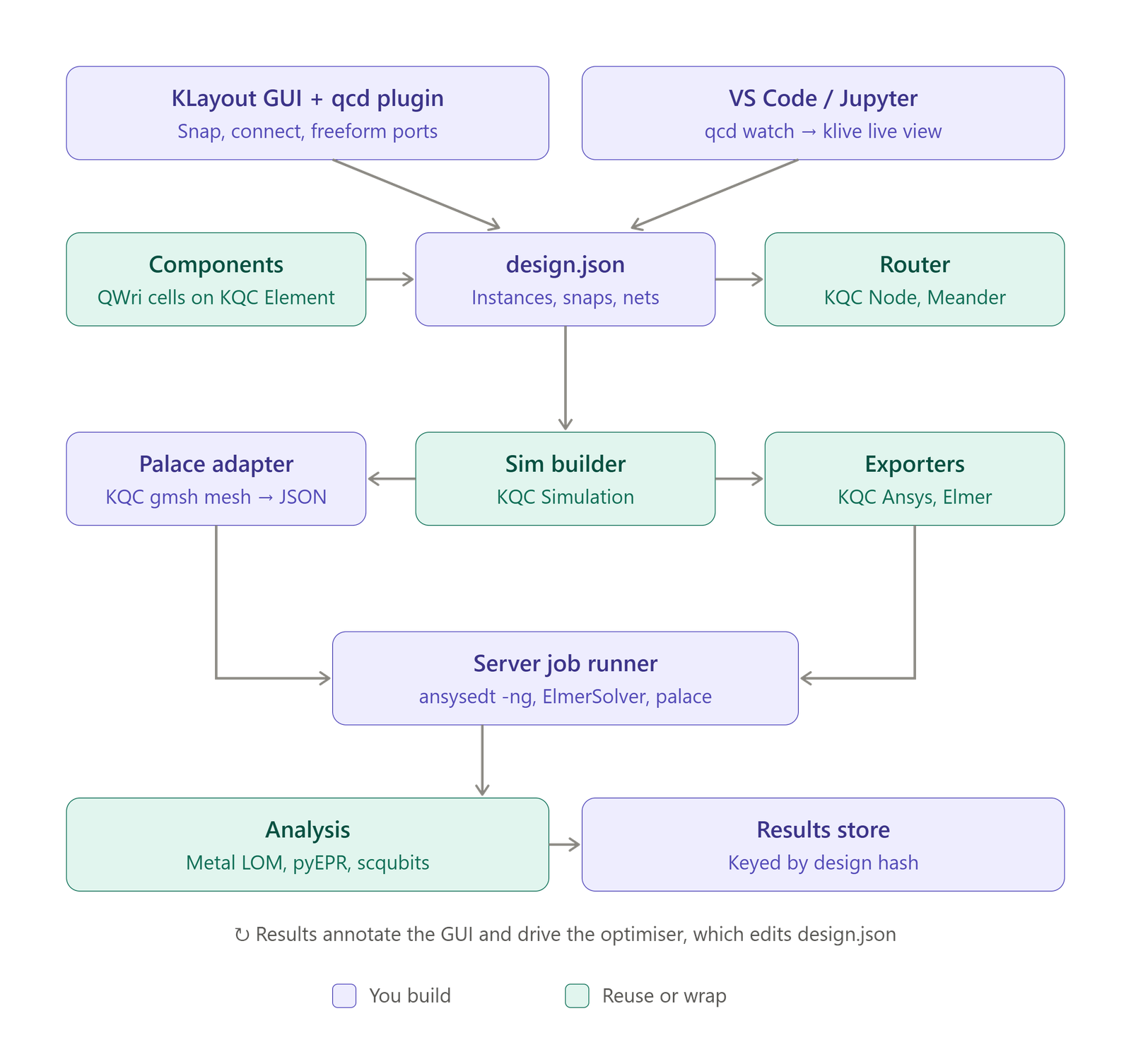
The original architecture sketch. The package is now quantcore_circuits (command qcc), the dashboard is a web app,
and the plugin is Quantcore’s own, not KQCircuits’. The as-built diagram above shows what exists.