IBM 27-qubit Falcon¶
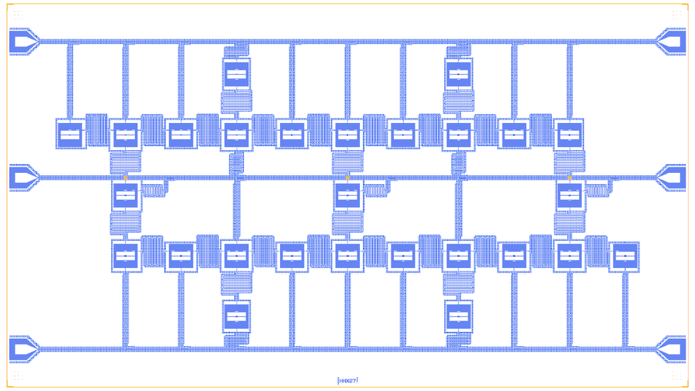
IBM’s heavy-hex lattice cut as the 27-qubit Falcon (ibmq_montreal): fixed-frequency transmons on the vertices and edges of a hexagonal lattice, each pair coupled by a resonant bus. It is two rows of ten qubits, three bridge qubits and four spur qubits. No layout is public; IBM’s device data give the graph and targets, and the layout is ours.
This notebook generates a lattice from a graph: a heavy_hex(rows) helper makes the 27 qubits and 28 edges, then the notebook places pockets, hangers on three feedlines and one λ/2 bus per edge. It is a large build (33 instances, 58 routes).
At a glance¶
Notebook |
|
Source |
IBM published device data (ibmq_montreal coupling map); Chamberland et al., PRX 10, 011022 (2020); no public layout |
Chip |
27 × 15.2 mm Quantcore die, sapphire 650 µm (εr 10.25) |
On the chip |
27 pocket transmons · 27 λ/4 hanger readouts · 28 λ/2 buses · 3 feedlines · 6 bond pads |
Builds today |
yes (layout built on 2026-11-19 in 28 s) |
How the notebook builds it¶
Each Design segment is one cell with a picture of the chip so far (see the notebook template).
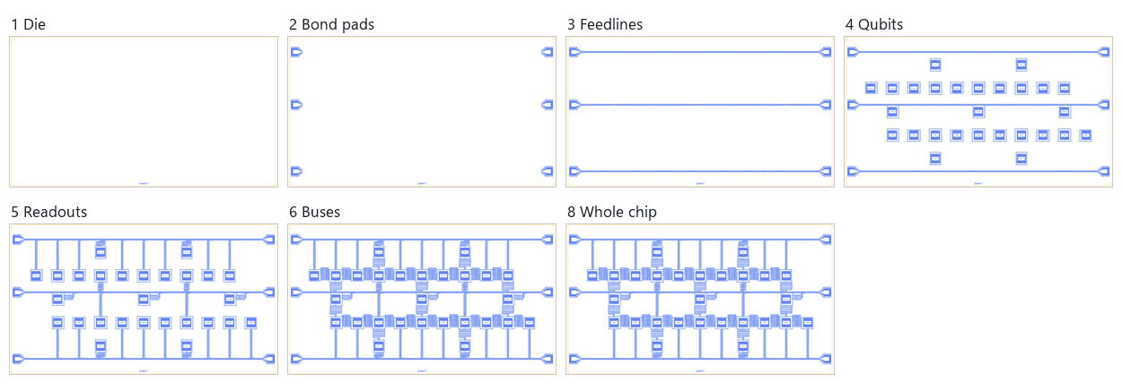
Die. A die sized to the lattice (2.5 mm margins round ten 2.2 mm columns), with the QCT frame and the device ID
HHX27.Bond pads. The three feedlines’ pads on the west and east edges.
Feedlines. Three straight feedlines; the middle one crosses the three bridge buses on airbridges.
Qubits. 27
TransmonPocket6pockets with trilayer junctions, and their bus and readout pads.Readouts. 27 λ/4 readouts, each ending in a 300 µm hanger.
Coupling. 28 λ/2 meander buses, one per edge.
Control lines. None: the planar die drives qubits through the feedlines.
Whole chip. The centring check, targets, sim groups and the save.
LOM estimates¶
Numbers are from the saved output of the .v1 notebook (this chip was not re-run for these docs): QuCat normal modes with QuTiP dressed values, each qubit solved with its readout and the feedline. IBM’s measured values are left out.
group |
qubit |
f_q (GHz) |
α (MHz) |
resonator |
f_r (GHz) |
κ (MHz) |
χ (MHz) |
|---|---|---|---|---|---|---|---|
Q0+R0 |
Q0 |
4.929 |
-151 |
R0 |
7.16 |
0.317 |
-0.422 |
Q1+R1 |
Q1 |
4.826 |
-144 |
R1 |
7.271 |
0.331 |
-0.347 |
Q2+R2 |
Q2 |
4.966 |
-146 |
R2 |
7.152 |
0.316 |
-0.47 |
Q3+R3 |
Q3 |
5.101 |
-145 |
R3 |
7.286 |
0.333 |
-0.603 |
Q4+R4 |
Q4 |
5.027 |
-147 |
R4 |
7.215 |
0.324 |
-0.385 |
Q5+R5 |
Q5 |
5.01 |
-146 |
R5 |
7.229 |
0.325 |
-0.577 |
Q6+R6 |
Q6 |
4.968 |
-150 |
R6 |
7.328 |
0.339 |
-0.504 |
Q7+R7 |
Q7 |
4.914 |
-143 |
R7 |
7.082 |
0.307 |
-0.6 |
Q8+R8 |
Q8 |
4.92 |
-143 |
R8 |
7.088 |
0.307 |
-0.406 |
Q9+R9 |
Q9 |
5.063 |
-149 |
R9 |
7.33 |
0.339 |
-0.541 |
Q10+R10 |
Q10 |
5.074 |
-146 |
R10 |
7.159 |
0.317 |
-0.412 |
Q11+R11 |
Q11 |
5.01 |
-146 |
R11 |
7.225 |
0.325 |
-0.577 |
Q12+R12 |
Q12 |
4.967 |
-143 |
R12 |
7.321 |
0.338 |
-0.377 |
Q13+R13 |
Q13 |
4.871 |
-147 |
R13 |
7.218 |
0.324 |
-0.423 |
Q14+R14 |
Q14 |
4.961 |
-142 |
R14 |
7.274 |
0.331 |
-0.568 |
Q15+R15 |
Q15 |
5.028 |
-147 |
R15 |
7.285 |
0.333 |
-0.372 |
Q16+R16 |
Q16 |
5.055 |
-145 |
R16 |
7.166 |
0.317 |
-0.618 |
Q17+R17 |
Q17 |
5.063 |
-149 |
R17 |
7.333 |
0.339 |
-0.54 |
Q18+R18 |
Q18 |
4.961 |
-142 |
R18 |
7.084 |
0.307 |
-0.623 |
Q19+R19 |
Q19 |
4.966 |
-143 |
R19 |
7.093 |
0.308 |
-0.421 |
Q20+R20 |
Q20 |
5.063 |
-149 |
R20 |
7.34 |
0.34 |
-0.539 |
Q21+R21 |
Q21 |
5.074 |
-146 |
R21 |
7.235 |
0.326 |
-0.396 |
Q22+R22 |
Q22 |
5.056 |
-145 |
R22 |
7.224 |
0.325 |
-0.6 |
Q23+R23 |
Q23 |
4.966 |
-146 |
R23 |
7.3 |
0.335 |
-0.438 |
Q24+R24 |
Q24 |
5.059 |
-145 |
R24 |
7.17 |
0.318 |
-0.503 |
Q25+R25 |
Q25 |
4.915 |
-143 |
R25 |
7.279 |
0.332 |
-0.547 |
Q26+R26 |
Q26 |
5.015 |
-149 |
R26 |
7.17 |
0.318 |
-0.564 |
pair |
f_a (GHz) |
f_b (GHz) |
J (MHz) |
target J (MHz) |
ZZ (kHz) |
|---|---|---|---|---|---|
Q3-Q5 |
5.104 |
5.012 |
1.46 |
1.49 |
70.7 |
Q5-Q8 |
5.012 |
4.92 |
1.52 |
1.41 |
74.5 |
Q8-Q11 |
4.92 |
5.012 |
1.11 |
1.47 |
51.1 |
Q11-Q14 |
5.012 |
4.966 |
1.52 |
1.4 |
51.9 |
Q14-Q16 |
4.966 |
5.058 |
1.17 |
1.55 |
56.4 |
Q16-Q19 |
5.058 |
4.966 |
1.62 |
1.47 |
84.4 |
Q19-Q22 |
4.966 |
5.058 |
1.17 |
1.49 |
57 |
Q22-Q25 |
5.058 |
4.92 |
1.62 |
1.36 |
476 |
Q25-Q26 |
4.92 |
5.015 |
1.18 |
1.43 |
56.4 |
Q0-Q1 |
4.928 |
4.825 |
1.3 |
1.31 |
58.3 |
Q1-Q4 |
4.825 |
5.027 |
0.895 |
1.32 |
-25.3 |
Q4-Q7 |
5.027 |
4.92 |
1.39 |
1.44 |
76.9 |
Q7-Q10 |
4.92 |
5.073 |
0.994 |
1.42 |
-261 |
Q10-Q12 |
5.073 |
4.966 |
1.49 |
1.58 |
88.6 |
Q12-Q15 |
4.966 |
5.027 |
1.05 |
1.49 |
31.4 |
Q15-Q18 |
5.027 |
4.966 |
1.39 |
1.7 |
45.9 |
Q18-Q21 |
4.966 |
5.073 |
1.05 |
1.49 |
58.8 |
Q21-Q23 |
5.073 |
4.965 |
1.58 |
1.42 |
101 |
Q2-Q3 |
4.962 |
5.104 |
1.5 |
1.36 |
1.08e+03 |
Q1-Q2 |
4.819 |
4.965 |
1.31 |
1.4 |
-1.81e+03 |
Q13-Q14 |
4.867 |
4.966 |
1.26 |
1.36 |
78.4 |
Q12-Q13 |
4.96 |
4.87 |
1.55 |
1.36 |
81.1 |
Q24-Q25 |
5.055 |
4.92 |
1.59 |
1.51 |
336 |
Q23-Q24 |
4.962 |
5.058 |
1.5 |
1.3 |
100 |
Q8-Q9 |
4.913 |
5.062 |
1.55 |
1.42 |
2.02e+03 |
Q19-Q20 |
4.96 |
5.062 |
1.64 |
1.46 |
126 |
Q6-Q7 |
4.967 |
4.92 |
1.37 |
2.01 |
42.1 |
Q17-Q18 |
5.062 |
4.966 |
1.54 |
1.52 |
77 |
The pair table lists the exchange coupling J and the static ZZ for the 29 qubit-bus-qubit edges. The edges Q22-Q25 (476 kHz), Q2-Q3 (1.08 MHz), Q1-Q2 (-1.81 MHz) and Q8-Q9 (2.02 MHz) are frequency collisions: the PDK’s α of about -145 MHz puts IBM’s neighbour detunings near |α|.
These are lumped-model estimates (component formulas and calibration), not FEM results. The LOM page says how far to trust them.
Build spec¶
The rest of this page is the detailed spec the notebook was built from, with every component, port, route and length.
Sources.
Device data (primary): Qiskit
FakeMontrealbackend filesconf_montreal.json/props_montreal.jsonfromqiskit-ibm-runtime(Apache-2.0; ibmq_montreal, Falcon r4, snapshot 2021-03-15; local copybuild/external/qiskit_fake_backends/): the 28-edge coupling map, f_q 4.835–5.105 GHz, α −308 … −390 MHz, J (jq) 1.31–2.01 MHz on every edge, measurement LO centres 7.19–7.46 GHz (all values in the notebook’s cell 1).Lattice: Chamberland, Zhu, Yoder, Hertzberg, Cross, “Topological and subsystem codes on low-degree graphs with flag qubits”, PRX 10, 011022 (2020) (arXiv:1907.09528): heavy-hexagon lattice, degree ≤ 3, cross-resonance gates on “fixed-frequency transmon qubits via microwave-resonant buses”, typical f01 ≈ 5 GHz, α ≈ −330 … −340 MHz; IBM Research blog “The IBM Quantum heavy hex lattice” (2021).
Device: Jurcevic et al., “Demonstration of quantum volume 64 on a superconducting quantum computing system”, Quantum Sci. Technol. 6, 025020 (2021) (arXiv:2008.08571): ibmq_montreal, qubits on a die bump-bonded to an interposer for signal delivery and readout.
Licence. Apache-2.0 data, papers cited; no heavy-hex layout is public (searched GitHub, Qiskit Metal, SQuADDS); layout and code ours (GPL).
What it is. 27 fixed-frequency floating transmons on the Falcon heavy-hex cut: two long rows of ten (bottom columns 1–10, top 0–9), three bridge qubits (columns 1, 5, 9), four spurs (columns 3, 7 above and below); one λ/2 meander bus per edge (28); a λ/4 readout per qubit on three horizontal feedlines (top: above the top spurs; middle: through the band between the rows, with airbridges over the three upper bridge buses; bottom: below the bottom spurs).
Generator. heavy_hex(rows, offset=1) (notebook cell 1): long rows → bridges at c ≡ offset + 2r (mod 4) → spurs.
Falcon = heavy_hex([(1, 10), (0, 9)]); heavy_hex([(0, 13)] + [(0, 14)] * 5 + [(1, 14)], offset=0, spurs=False) gives the
127-qubit, 144-edge Eagle graph (a layout of it needs more feedlines).
Chip. 27.0 × 15.2 mm, Quantcore die frame (QCT), device ID HHX27; sapphire 650 µm, εr 10.25; 10/6 µm CPW;
column pitch 2200 µm, level pitch 2400 µm. Junctions: Quantcore trilayer, L_J per qubit 6.49–7.17 nH (R_n 43–48 kΩ).
Notebook. examples/designs/ibm/ibm_falcon_27q.ipynb.
Components and routes¶
item |
ref / type |
notes |
|---|---|---|
Q0 … Q26 |
metal:TransmonPocket6 |
pads 750 × 160, gap 20, pocket 950; bus pads 125 (corners ±x at +190 µm for row edges, middles ±y for vertical edges), readout pad 120 |
B_a_b (28) |
meander route |
λ/2; row edges 6.2 / 6.5 GHz alternating, vertical edges 6.35 GHz (assumed); length 60 400 / f µm (calibrated) |
R0 … R26 |
meander → hanger |
λ/4 3975–4121 µm, hanger 300 µm, ground gap 4, short; bridges’ readouts leave a corner pad and run +x 1 mm first |
FL_top, FL_mid, FL_bot |
cpw |
BondPads on the side edges; FL_mid has airbridges at columns 1, 5, 9 |
Targets and LOM values¶
quantity |
IBM |
rebuild (LOM) |
|---|---|---|
f_q |
4.835–5.105 GHz |
4.826–5.101 GHz, every qubit within 30 MHz (per-qubit L_J solved) |
α |
−308 … −390 MHz |
≈ −145 MHz (PDK window) |
readout |
7.19–7.46 GHz |
within 3 MHz; κ 0.32–0.35 MHz, χ −0.33 … −0.57 MHz |
buses |
– |
6.23 / 6.51 / 6.37 GHz (row even / row odd / vertical) |
J |
1.31–2.01 MHz |
0.84–1.51 MHz (bus pads 125 µm; the 6.5 GHz buses give the low end); ZZ 27–107 kHz on 22 edges |
Simplifications / adaptations¶
Planar single die (Falcon: qubit die + interposer): readout on three feedlines with three airbridges, no drive lines (drive through the feedlines), no Purcell filters. α about half of IBM’s (PDK junction window). Bus frequencies are not published: assumed plan.
Frequency collisions. IBM’s frequency pattern assumes α ≈ −330 MHz. With the PDK’s α ≈ −145 MHz, neighbour detunings of 0.1–0.2 GHz sit near |Δ| ≈ |α| and the static ZZ becomes large on six edges: Q8–Q9 1.83 MHz, Q1–Q2 −1.71 MHz, Q2–Q3 0.93 MHz, Q22–Q25 0.40 MHz, Q24–Q25 0.29 MHz, Q7–Q10 −0.23 MHz. A Quantcore heavy-hex chip needs Chamberland §II C’s allocation redone for its α, or a junction window that reaches larger α.