Component examples (Metal A–E)
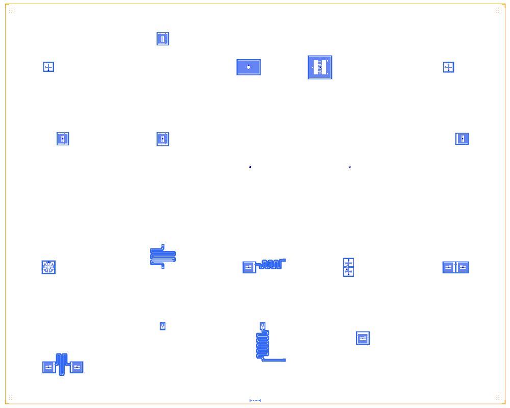
A catalogue board rather than a chip. The 19 single-component and sub-circuit notebooks of the Qiskit Metal “circuit examples” (qubits, resonators, composites, couplers, input-output coupling; Apache-2.0, © IBM and contributors) are gathered on one 35 × 28 mm board, one 7 × 7 mm tile each. The Quantcore rebuild is distributed under GPL-3.0.
Build this one to see every metal: component drawn through the wrapper in one place, with Quantcore junctions. The
board is a test bed for the component wrappers and their LOM models and is not meant for fabrication.
At a glance
Notebook |
|
Source |
Qiskit Metal circuit examples A.Qubits, B.Resonators, C.Composite-bi-partite, D.Qubit-couplers, E.Input-output-coupling, © IBM and contributors, Apache-2.0 |
Chip |
35 × 28 mm board of 7 × 7 mm tiles (larger than the 7.5 mm Quantcore die) |
On the chip |
19 example tiles: qubits (A), one resonator (B), one qubit with a resonator (C), three coupler examples (D), launchpad and charge-line examples (E) |
Builds today |
yes (layout built on 2026-11-19 in 14 s) |
How the notebook builds it
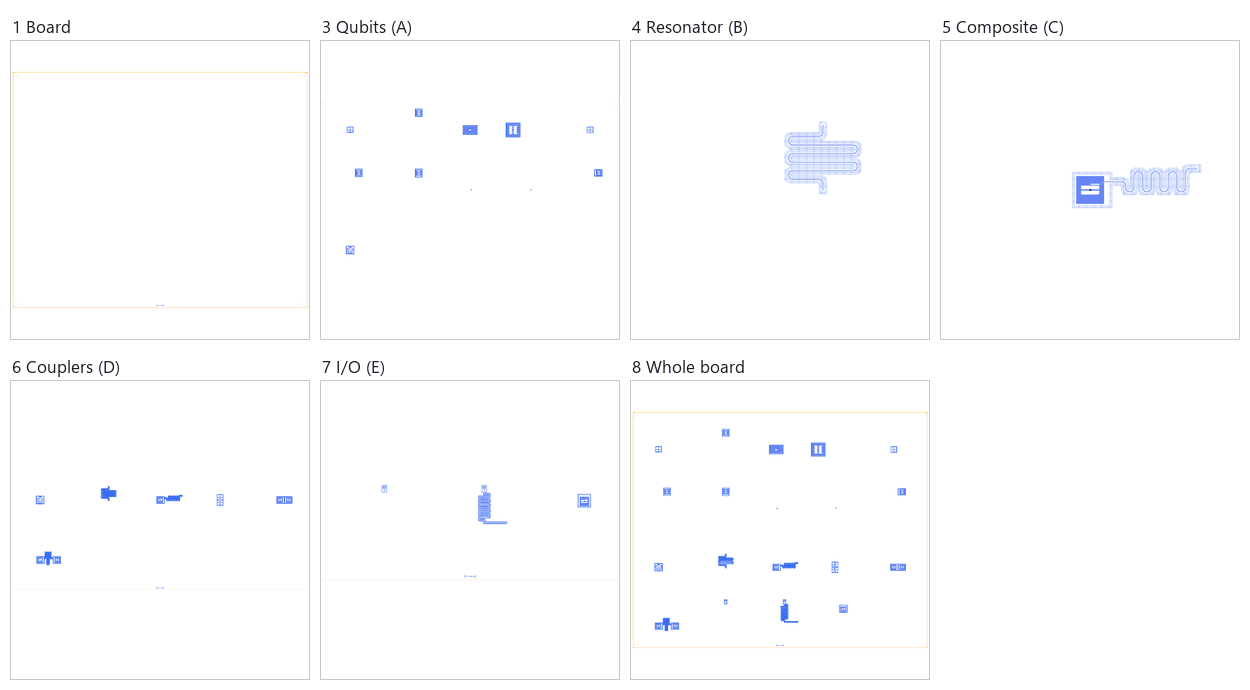
Board. An empty board with the QCT frame and the 5 × 4 tile grid.
Bond pads. None placed: the pad rule is not applied to this board (its two launchpads stay in their tiles).
Qubits (A). The qubit examples, each with a Quantcore junction.
Resonator (B). One λ/2 meander between two open ends.
Composite (C). A pocket transmon with its 5 mm meander.
Couplers (D). Two crossmons with a tunable coupler, and two pockets joined by a short line and by a bus.
Input-output (E). A coupled launchpad, a launchpad driving an open meander, and a pocket with a charge line.
Whole board. Sim groups for the FEM jobs, the content centred in the die, the design saved.
Each picture in the strip zooms on the tiles of that group.
LOM estimates
Numbers are from a run of this notebook on 2026-11-19 (Setup, Design, Check and the LOM cells, 18 s): QuCat normal modes with QuTiP dressed values.
group |
qubit |
f_q (GHz) |
α (MHz) |
resonator |
f_r (GHz) |
κ (MHz) |
χ (MHz) |
|---|---|---|---|---|---|---|---|
A01 |
A01_Q1 |
5.818 |
-201 |
– |
– |
– |
– |
A02 |
A02_Q1 |
7.087 |
-310 |
– |
– |
– |
– |
A03 |
A03_qubit1 |
5.48 |
-177 |
– |
– |
– |
– |
A04 |
A04_qubit1 |
4.065 |
-87.9 |
– |
– |
– |
– |
A05 |
A05_Q1 |
5.818 |
-201 |
– |
– |
– |
– |
A06 |
A06_Q1 |
7.094 |
-310 |
– |
– |
– |
– |
A07 |
A07_Q1 |
7.087 |
-310 |
– |
– |
– |
– |
A10 |
A10_Q1 |
7.759 |
-379 |
– |
– |
– |
– |
A11 |
A11_Star |
5.174 |
-156 |
– |
– |
– |
– |
B11 |
– |
– |
– |
B11_meanderTest |
7.002 |
0 |
– |
C21 |
C21_Q1 |
7.349 |
-334 |
C21_coupler |
11.73 |
0 |
-2.52 |
D32 |
D32_Q1 |
7.353 |
-286 |
– |
– |
– |
– |
D33 |
D33_Q1 |
7.342 |
-322 |
D33_coupler |
11.02 |
0 |
-2.79 |
E42 |
– |
– |
– |
E42_bus |
6.235 |
2.01 |
– |
E43 |
E43_Q1 |
7.087 |
-310 |
– |
– |
– |
– |
D31_Q1 |
D31_Q1 |
5.788 |
-199 |
– |
– |
– |
– |
D31_Q2 |
D31_Q2 |
5.788 |
-199 |
– |
– |
– |
– |
D31_Tune_C_Q12 |
D31_Tune_C_Q12 |
8.568 |
-474 |
– |
– |
– |
– |
group |
pair |
ZZ (kHz) |
neighbours |
hybridised |
|---|---|---|---|---|
D32 |
D32_Q1-D32_Q2 |
– |
yes |
yes |
D33 |
D33_Q1-D33_Q2 |
– |
yes |
yes |
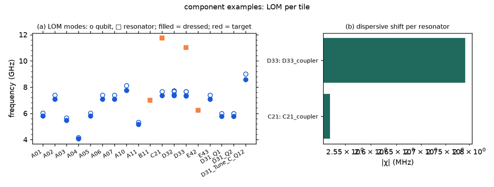
These are lumped-model estimates from component formulas and calibration, not FEM results. The LOM page says how far to trust them.
Build spec
The rest of this page is the detailed spec the notebook was built from: every component, port, route and length.
The
metal:references in this spec build as written, through themetal:wrapper (ports are the Metal pin names, parameters the Metal options). The Quantcore and KQC substitutions are optional.
The notebook
examples/designs/metal/component_examples.ipynbbuilds all 19 A–E notebooks, run headless, one 7 × 7 mm tile each.
Source: Quantum Metal docs/circuit-examples/{A.Qubits, B.Resonators, C.Composite-bi-partite, D.Qubit-couplers, E.Input-output-coupling} plus analysis sub-circuits from docs/tut/**. Licence Apache-2.0.
None of these is a whole chip (no launchpads plus readout plus control). They are useful as component tests for the
metal:<Class> wrappers and for the LOM models. Coordinates are Metal (centred); the chip size is given where the
notebook sets it.
circuit-examples, A–E
notebook |
what it draws |
catalog refs (buildable stand-in) |
|---|---|---|
A.Qubits/01-Transmon_cross |
one TransmonCross |
metal:TransmonCross ( |
A.Qubits/02-Transmon_floating |
one TransmonPocket |
metal:TransmonPocket (KQC |
A.Qubits/03-concentric_transmon |
one TransmonConcentric |
metal:TransmonConcentric (KQC |
A.Qubits/04-Interdigitated_Transmon |
TransmonInterdigitated |
metal:TransmonInterdigitated (no direct KQC match) |
A.Qubits/05-Transmon_cross_fl |
TransmonCrossFL |
metal:TransmonCrossFL ( |
A.Qubits/06-Transmon_floating_6 |
TransmonPocket6 |
metal:TransmonPocket6 (none with 6 couplers) |
A.Qubits/07-Transmon_floating_cl |
TransmonPocketCL |
metal:TransmonPocketCL ( |
A.Qubits/08-JJ-Dolan, 09-JJ-Manhattan |
junction cells |
metal:jj_dolan, metal:jj_manhattan (KQC |
A.Qubits/10-Transmon_floating_teeth |
TransmonPocketTeeth |
metal:TransmonPocketTeeth |
A.Qubits/11-Star_shaped_qubit |
StarQubit |
metal:StarQubit (used by 53/54) |
B.Resonators/11-Resonator_Meander |
RouteMeander to OpenToGround |
meander route plus |
C.Composite-bi-partite/21-OneTransmonsWithMeanderAndOTG |
TransmonPocket + 5 mm meander to an open end (chip 4 × 6 mm) |
pocket stand-in plus meander plus |
D.Qubit-couplers/31-TwoCrossmonsTunableCoupler |
2 TransmonCrossFL ± 0.3 mm + TunableCoupler01 (chip 3 × 3 mm) |
sub-circuit of |
D.Qubit-couplers/32-TwoTransmonsDirectCoupling |
2 TransmonPocket 1 mm apart + RouteStraight between readout pads (chip 2 × 2 mm) |
two Xmons plus a straight cpw |
D.Qubit-couplers/33-TwoTransmonsWithMeander |
2 TransmonPocket 2 mm apart + 5 mm meander bus (chip 4 × 6 mm) |
two Xmons plus a meander bus |
E.Input-output-coupling/41-LaunchPad |
LaunchpadWirebondCoupled |
|
E.Input-output-coupling/42-ResonatorAndLaunchPad |
coupled pad → 10 mm meander → open end |
BondPad + cap + meander + free end |
E.Input-output-coupling/43-TransmonPocketCL |
TransmonPocketCL |
as A.07 |
Tutorial sub-circuits (not whole chips)
notebook |
what it draws |
|---|---|
tut 1.4 Saving-Your-Chip-Design |
2 TransmonPocketCL + 2 pads, explicit full option dumps (useful default reference) |
tut 1.5 Parametric-design |
the 4-qubit ring of 1.3 swept over options |
tut 2.12–2.15 routing |
meander/anchor/mixed/airbridge routing demos between pockets |
tut 2.24 Design-rule-checking |
deliberately bad routes (thin gap, kink, airbridges) on a 6 × 6 mm chip, for DRC tests |
tut 3.1–3.3, 4.01, 4.21, quick-topics/Managing-pins |
1.3-style 4-pocket core, render/LOM demos |
tut 4.13 / 4.14 |
transmon + resonator; double hanger (2 pockets, 2 CLTs, 8/9 mm meanders, chip 2 × 2 mm) |
tut 4.16–4.18 |
hanger resonator test chips (LaunchpadWirebondDriven ×2, CLT, meander, OTG; chip 9 × 9 mm), S21 fits |
tut 4.19 |
single transmon C-matrix with ElmerFEM |
tut Design-and-Simulation-of-a-Cross-Resonance-Gate |
2 TransmonPocket6 1 mm apart + meander coupler (CR-gate pair, no readout) |
tut 4.44–4.46 |
the same 10 × 10 package device as |
Use
Use these as unit tests for each
metal:<Class>wrapper (ports = Metal pin names) and for the per-component LOM models before building the chips.The 4.16–4.18 hanger chips validate the Designer hanger’s κ and Q_ext. They need
metal:LaunchpadWirebondDriven(or a BondPad port).
Quantcore PDK rebuild
The notebook is a Quantcore PDK rebuild of the source, not a replica: the netlist, LOM and imported components are kept, and the process is Quantcore’s.
Notebook: examples/designs/metal/component_examples.ipynb.
Chip: the Quantcore die frame (L dicing markers 1000/0, 3 × 3 alignment grids 1001/0, chip boundary 100/0, device ID where an edge is free; any brand text is QCT), drawn on the source’s 35 × 28 mm chip (the design does not fit the 7.5 mm die); no KQC chip frame.
Stack: sapphire 650 µm, εr 10.25 (the PDK default stack, used by the LOM estimates and every FEM export); Metal’s
DesignPlanardefault is silicon (εr 11.45, 750 µm), so the LOM capacitances, resonator frequencies and FEM jobs here are for sapphire rather than the source’s substrate.Junctions: Quantcore Nb/AlOx/Nb trilayer junctions (
junction_typefromlayouts.registry.trilayer_junction): fingers on 2/0 + 4/0, spacer 50/0 with the 51–53/0 gradient, sized on the PDK junction rule (Nb Δ = 1.4 meV, I_c·R_n = πΔ/2e, R_n·A 13.5 kΩ·µm² and C_J 50 fF/µm² assumed); every qubit gets the PDK nominal junction, 0.5 × 0.6 µm fingers → R_n = 45 kΩ, L_J = 6.73 nH, C_J = 15 fF (in the 40–50 kΩ window), the flux-tunable cells (TransmonCrossFL,TunableCoupler01) a PDK SQUID of two 0.25 × 0.6 µm junctions → R_n = 45 kΩ in parallel, L_J = 6.73 nH at zero flux, C_J = 15 fF (in the 40–50 kΩ window), in place of the 10 nH + 2 fF assumed for the source. The interdigitated transmon (C_Σ ≈ 216 fF) is sized for 4.05 GHz (L_J 6.4 nH, R_n ≈ 43 kΩ) to stay in the 4–8 GHz band. Expected (estimates from the LOM): crosses ≈ 5.8 GHz, pockets ≈ 7.1–7.4 GHz, Teeth ≈ 7.7 GHz, concentric ≈ 5.5 GHz, star ≈ 5.2 GHz, the D.31 coupler ≈ 8.6 GHz at zero flux. The two junction tiles (A.08jj_dolan, A.09jj_manhattan) keep Metal’s own junction drawing as a reference (single-layer, 2/0 only, so not a Quantcore junction).Kept: the topology and every Metal component with the source’s options (through the
metal:wrapper), positions and orientations, every route’s end pins and total length, the sim groups (each example on its own 7 × 7 mm tile, Metal’s route corner points and lengths).