Routing and DRC
This page covers the design.json file, how a design becomes a layout with its routes, and the design rule check
(DRC) that reports what is wrong. You need it when a route fails, when the DRC shows a warning you do not
understand, or when you want to read or write design.json yourself.
design.json
design.json (pydantic schema qcc/0.1, design/schema.py) holds instances (cell, params, place, junction),
routes (CPW or meander, nodes, hanger and free ends), chip, targets and sim_groups. qcc design validate checks
a file, qcc design hash gives its canonical hash, and qcc design to-python writes a Python script that rebuilds it
(a round trip, checked on 105 examples on 2026-11-15). A field reference is not written yet (a table can be generated
from Design.model_json_schema()).
Build and routing
assembly.build(design, keep_going=, last_good=) solves the snaps in dependency order, applies the pad rule and
junction defaults, and gives a KQC DesignChip. route/router.py plans routes: waveguides, meanders (fix_length),
hangers, free ends, T-merges, airbridges and per-corner radii. qcc build DESIGN [--keep-going --label-height --show]
is the command.
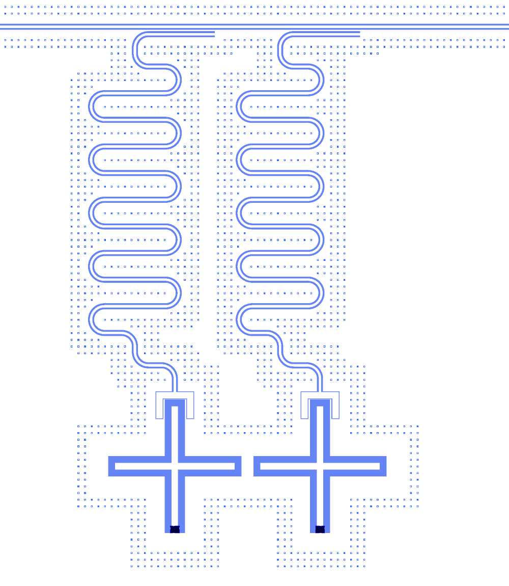
Two lambda/4 readouts, each a meandered route from a qubit claw to a hanger on the shared feedline (tutorial 4).
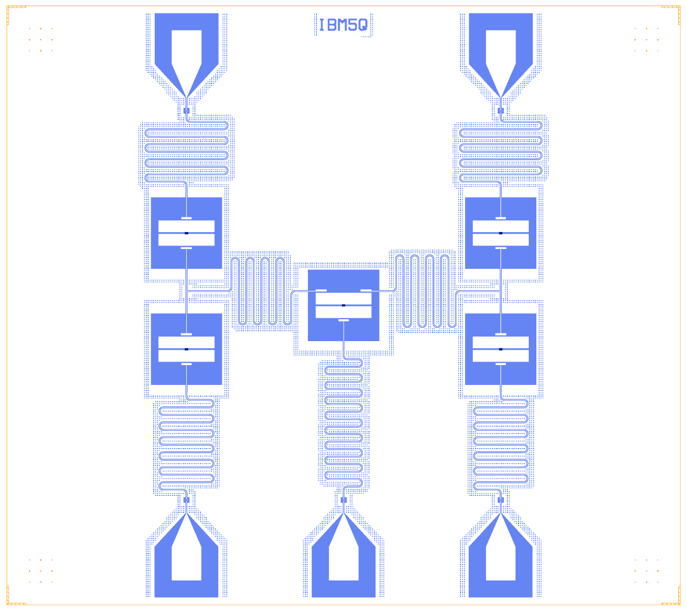
Lambda/2 bus resonators with tees and individual readout lines (tutorial 2, the IBM bowtie).
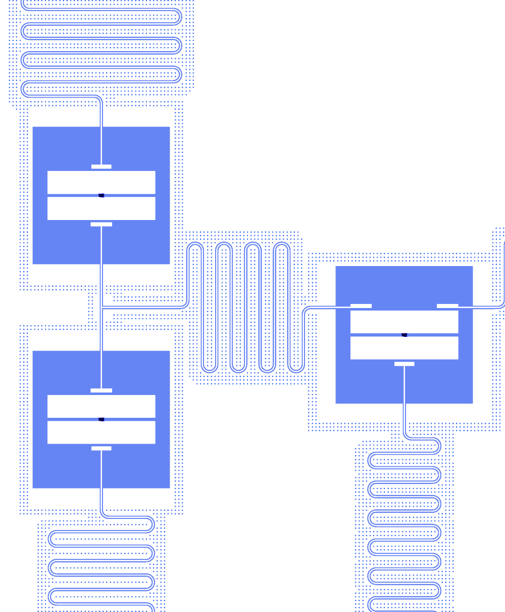
One triangle of the bowtie: two pockets, the tee and its stubs, the bus meander.
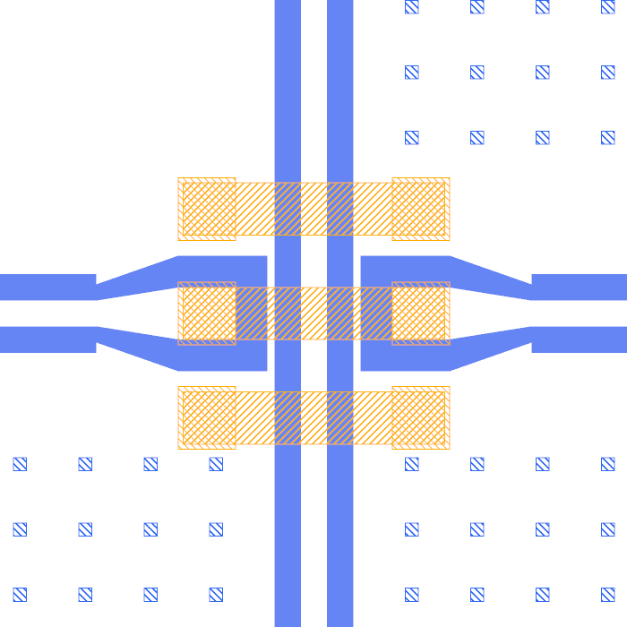
Airbridges (orange) over a crossing: a line crossing another is split into sections joined by AirbridgeConnection
instances (tutorial 3).
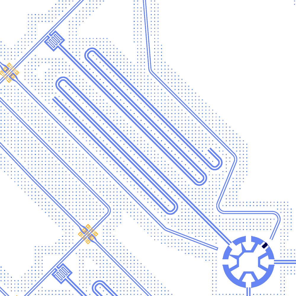
A readout module of the 17-qubit chip: hairpin readout, Purcell filter and tee with bridged lines.
Angled ports and the rotation snap are shown on the plugin tour; failed routes are shown there too.
With --keep-going (what the plugin uses) a route that cannot be built is left out and reported, and the last good
path is kept in build/<name>.last_good_routes.json. Plain qcc build is strict and stops at the first bad route.
Length fixing
A route with a target length (a meander) goes through route/router.fix_length, which compares the target with the
path as drawn:
within 0.01 µm: the path is kept and gets no meander;
slightly short: the radius of its free corners is trimmed by up to 5 %;
otherwise: a KQC meander on the longest free straight, with no more turns than keep it at least one bend radius wide, so it never flattens into a zigzag. If fewer turns than you asked for fit, a warning says so.
A target shorter than the shortest path is an error.
Tapers on waypoints
A waypoint with its own a and b becomes a KQC taper that starts at the waypoint and runs taper_length (100 µm by
default) forward. If the straight after the waypoint is shorter than the taper, KQC would draw the taper past the next
node or the route’s end and run the line back over it: the etch would reach beyond the port, and the route length
would count the overshoot twice. The router then has KQC start that taper taper_length before the waypoint, so the
taper ends at the waypoint and the new width runs from there to the next node. The waypoint itself stays where the
design puts it (the route’s polyline, the plugin’s handles and the waypoint indices do not change). A route that
widens 51 µm before its end and the mirror route that narrows 51 µm after its start both measure their straight
length:
d.route("FEED_IN", "PIN.a", "T_F.a", nodes=[d.waypoint((834, 6000), a=40, b=24)], taper_length=100)
# taper 734 → 834 µm, then 51 µm at a = 40 µm up to the port at x = 885 µm
This is done only when the straight before the waypoint has room for the taper. Otherwise the route is built as KQC draws it.
Known limits
A node closer to a corner than the bend’s cut fails in KQC (“Straight segment cannot fit”), and a waypoint on a port
axis at a distance between r and 2r fails. Both are open items of the router. A route that hits one is reported and, with --keep-going, left out.
DRC and netlist
assembly.drc.check(source, netlist=True) returns a DrcReport of DrcIssue(severity, rule, message, where, objects). The fast DRC runs on every build and is stored in the sidecar; netlist=True adds the KQC geometric netlist.
Severity |
Rules |
|---|---|
error / warning |
|
design (never enforced) |
|
Commands: qcc design drc, qcc design netlist, Designer.drc(), the plugin’s Check. In the notebooks the report is a
Markdown table:
DRC clean - 0 errors, 1 warnings, 0 PDK design warnings
| severity | rule | count | example |
| warning | dangling_port | 1 | Q1.claw_n is not connected (no route or snap) |
(tutorial 0, section 5). The DRC tab with markers is shown on the plugin tour.
Design warnings never block a build or an export; they tell you where the design is outside the PDK margins (see the
PDK page). The pad_edge rule counts Launcher, LauncherDC and TaperedPad cells as bond pads. Errors
and warnings are the checks of the design itself: a dangling port, an overlap, a route over a component. The cheese is
not part of the DRC: it is added at build and fab time (Fab export).
crossing compares the routes’ node polylines, so it does not see a meander, which KQC draws between two nodes. The
rules on built geometry do: route_overlap (centre conductors on top of each other), route_clearance (no ground
between the two gaps) and airbridge_short (an airbridge pad on another route) compare each pair of routes as built,
meanders included. Two routes that share a port, or a route and the line it hangs off, are skipped there, because
they meet on purpose. Two routes that end on one component at different ports, such as a bus and a readout resonator
on one qubit or two resonators on one coupler, are compared everywhere except around that component (its box grown
by the wider route’s half width a/2 + b), where their ports put them side by side.
Faces in flip-chip and TSV designs
A design can draw on KQC’s four faces: 1t1 (bottom chip, front), 1b1 (bottom chip, back), 2b1 (top chip, the
face looking down) and 2t1 (top chip, back). The DRC checks each face on its own.
overlap: two components overlap only if they draw on a common face. The DRC reads the faces from the built cell (thekqcircuits.defaults.default_faceslayers it has shapes on, avoidance and port texts left out) and not fromface_ids, because most KQC cells list all four faces there and draw on the first one only. The front and back pad of a TSV transition, or a qubit on2b1above a resonator on1t1, are not an overlap. A TSV or an indium bump (a cell with shapes only on via, bump and UBM layers) sits on another component’s metal on purpose: it overlaps that component only where the via or bump lands on its etch, and the message names that face. Two vias or two bumps on top of each other still overlap. A component with no shapes on any face layer (a static cell on fab layers) is compared with everything, as on a one-face chip.open_conductor: each route end is checked on the face it is drawn on, with that face’sbase_metal_gap_wo_gridetch. A route starts on the first entry of itsface_ids(else on the chip’s face,1t1) and changes face at each waypoint withface_id, sofromis checked on the start face andtoon the face after the last change. A route end on a face its component draws nothing on, such as a1b1route ending on a front-face pad, is anopen_conductorerror.crossing: a route is on itsface_ids[0], so a backside route passing under a front-face route is not a crossing. The rules on built geometry (route_overlap,route_clearance,route_self_overlap,route_over_component,airbridge_short) compare each face on its own as well.
A TSV transition with its two pads stacked, as QPDK draws it, and a backside route leaving the back pad, gives no
overlap and no open_conductor:
pad = dict(path=[[-15, 0], [15, 0]], a=40, b=24)
via = dict(face_ids=["1t1", "1b1"], tsv_diameter=10, tsv_elliptical_width=20, tsv_margin=2)
d.add("T_F", "WaveguideCoplanar", at=(900, 6000), term2=24, face_ids=["1t1", "1b1"], **pad)  # front pad
d.add("T_B", "WaveguideCoplanar", at=(900, 6000), term1=24, face_ids=["1b1", "1t1"], **pad)  # back pad
for k, dy in enumerate((-10, 10)):  # signal vias through the chip, under both pads
    d.add(f"T_SV{k}", "TsvEllipse", at=(900, 6000 + dy), **via)
d.route("UNDER", "T_B.b", "U_B.b", a=40, b=24, face_ids=["1b1"])  # U_B: the back pad of the next transition
What the DRC does not check yet: the component boxes it compares are the 1t1 etch box, or the whole cell box for a
cell with no 1t1 etch, so a backside component’s box is coarser than its etch. outside_chip and the frame rules
use the bottom chip’s box on every face, so a top-chip component is not checked against the top chip’s outline. The
DRC does not check that a transition’s vias sit under both of its pads; the netlist joins the pads only through the
declared wire coupling.