Six-Xmon chip (Litho)
Six Xmons in two columns of three, one each side of a vertical feedline, each with a λ/4 meander readout coupled to the feedline. The layout is the six-Xmon notebook of Qiskit-Metal-to-Litho (CC BY 4.0), rebuilt on the Quantcore PDK with a trilayer junction per qubit (L_J 15.904 nH).
This notebook is an example of a frequency-multiplexed readout on one feedline (six readouts, 6.116 to 6.704 GHz) and of moving a foreign design onto the PDK pad rule.
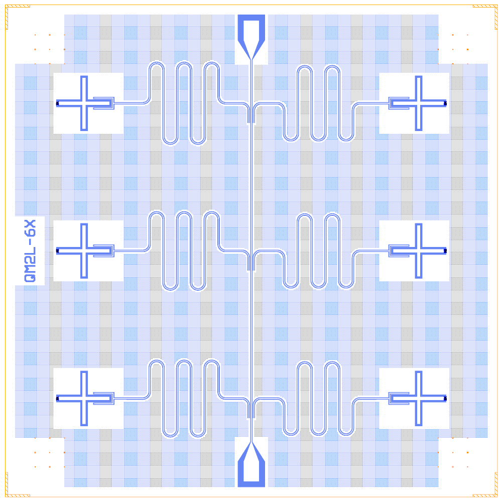
At a glance
Notebook |
|
Source |
Qiskit-Metal-to-Litho |
Chip |
5 × 5 mm Quantcore die (the source’s chip size), feedline 11.7 / 5.1 µm |
On the chip |
2 launchpads · 1 feedline · 6 Xmons · 6 λ/4 hanger readouts |
Builds today |
yes (layout built on 2026-11-19 in 23 s) |
How the notebook builds it
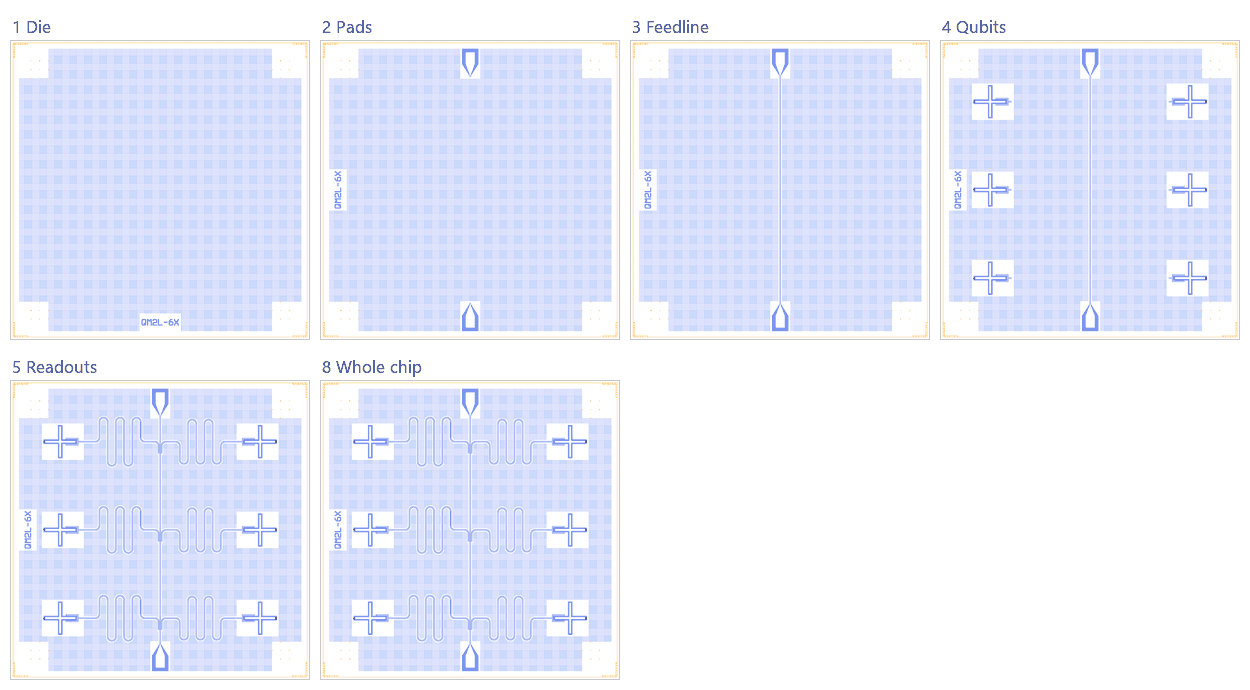
Die. The 5 × 5 mm die with the frame and the device ID
QM2L-6X.Bond pads. Two launchpads, moved to the 100 µm pad rule.
Feedline. A straight 11.7 / 5.1 µm line between the pads.
Qubits. Six Xmons with trilayer junctions.
Readouts. Six λ/4 hanger routes from the claws to the feedline.
Coupling. None: the qubits do not couple to each other.
Control lines. None.
Whole chip. Sim groups, targets, centring, save.
LOM estimates
Numbers are from a run of this notebook on 2026-11-19 (Setup, Design, Check and the LOM cells, 26 s): QuCat normal modes with QuTiP dressed values.
qubit |
f_q (GHz) |
α (MHz) |
resonator |
f_r (GHz) |
κ (MHz) |
χ (MHz) |
|---|---|---|---|---|---|---|
Q1_L |
3.183 |
-151 |
R_Q1_L |
5.431 |
0.0597 |
-0.124 |
Q2_L |
3.183 |
-151 |
R_Q2_L |
5.609 |
0.0655 |
-0.117 |
Q3_L |
3.183 |
-151 |
R_Q3_L |
5.698 |
0.0685 |
-0.113 |
Q1_R |
3.183 |
-151 |
R_Q1_R |
5.769 |
0.071 |
-0.111 |
Q2_R |
3.183 |
-151 |
R_Q2_R |
5.833 |
0.0733 |
-0.109 |
Q3_R |
3.183 |
-151 |
R_Q3_R |
5.869 |
0.0747 |
-0.108 |
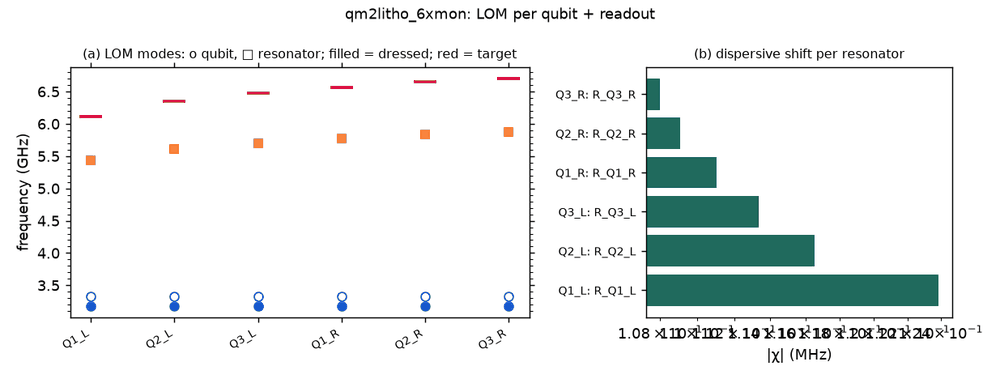
These are lumped-model estimates (component formulas and calibration), not FEM results. The LOM page says how far to trust them.
Build spec
The rest of this page is the detailed spec the notebook was built from, with every component, port, route and length.
Source: OJB-Quantum/Qiskit-Metal-to-Litho,
6_Xmon_Layout_with_Quantum_Metal_PHIDL_GDSTK_in_Colab.ipynb. Outputs GDS Files/six_xmon_quantum_metal.gds, the
_cheesing variant and six_xmon_quantum_metal_gaps.oas (not downloaded). Licence CC BY 4.0 (verified).
Read on 2026-11-02: notebook constants only.
What it is: 6 Xmons (TransmonCross) in two columns of 3, one each side of a straight vertical feedline. Each has a
λ/4 meander readout coupled through a CoupledLineTee (6.116–6.704 GHz). It is the same family and parameters as the
SQuADDS tutorial-5 qubit (Lj 15.904 nH). A second notebook section adds an antidot (vortex-hole) field.
Frame: chip 5 × 5 mm centred. Box (0, 0, 5000, 5000), Designer = source + (2500, 2500). Feedline 11.7/5.1 µm;
readout 10/6 µm. Layers 3/0 metal, 3/1 etch, 9 junction.
The chip needs Xmon, BondPad and hangers.
Components
instance |
catalog ref |
key params (units) |
at (x, y) Designer |
rot |
notes |
|---|---|---|---|---|---|
Q1_L / Q2_L / Q3_L |
|
cross tip-to-tip 520 (cross_length 260), arm_width 35, gap 20. Claw toward the feedline: claw_length 190, width 10, gap 6, ground spacing 5, claw stub 60 |
(800, 4000) / (800, 2500) / (800, 1000) |
claw faces +x |
Metal orientation −90, source x −1700, y 1500/0/−1500 |
Q1_R / Q2_R / Q3_R |
|
same |
(4200, 4000) / (4200, 2500) / (4200, 1000) |
claw faces −x |
orientation 90 |
WB_TOP / WB_BOT |
|
(2500, 4600) / (2500, 400) |
180 / 0 |
pos_y ±2100 |
Junction: junction={"Lj_nH": 15.9, "Cj_fF": 2} (Lj 15.903982 nH stated; Cj assumed).
Routes
route |
from → to |
type, length |
hanger (s, length, side, ground_gap) |
f_target |
|---|---|---|---|---|
FL |
WB_TOP.a → WB_BOT.a |
cpw 11.7/5.1 |
straight x 2500 (travel −y, left = +x) |
|
R_Q1_L |
Q1_L.claw → FL.hanger |
meander 4905 |
s ≈ 4600 − 4000 = 600 (from the pad port), 200, right, 4 |
6.116 |
R_Q2_L |
Q2_L.claw → FL.hanger |
4722 |
s ≈ 2100, 200, right, 4 |
6.353 |
R_Q3_L |
Q3_L.claw → FL.hanger |
4635 |
s ≈ 3600, 200, right, 4 |
6.472 |
R_Q1_R |
Q1_R.claw → FL.hanger |
4567 |
s ≈ 600, 200, left, 4 |
6.568 |
R_Q2_R |
Q2_R.claw → FL.hanger |
4508 |
s ≈ 2100, 200, left, 4 |
6.655 |
R_Q3_R |
Q3_R.claw → FL.hanger |
4475 |
s ≈ 3600, 200, left, 4 |
6.704 |
L = v/(4f) with v = 1.20e8 m/s. Frequencies are taken in site order (index-matched in the code). CLT: coupling_length 200, coupling_space 4 (ground strip, used as ground_gap), down_length 110. Meander spacing 240, fillet 70, leads 180/140; meander asymmetry ±90 alternates per row. Two hangers share each s (left and right of the line); that works because they sit on opposite sides.
Launchers, pads, test structures, markers, labels
2 pads. Cheesing variant: antidots 2 µm squares at 10 µm pitch, 15 µm keep-out, 45 µm around pads. Maps to
chip={"with_grid": True}.
LOM node structure
6 grounded Xmon islands (fixed JJ). Each has a claw C_g to its λ/4 R, which has κ to FL (two 50 Ω ports). No couplers or control lines.
Targets
Readout 6.116 / 6.353 / 6.472 / 6.568 / 6.655 / 6.704 GHz. Qubit about 3.66 GHz if it matches the SQuADDS DB entry (same cross and Lj; inferred, not stated).
Simplifications for a first rebuild
Build it as is. If two couplers at the same s clash with the Xmon claw approach, offset the right column’s s by ±50 µm.
Build
The notebook uses the Metal cells themselves (metal:TransmonCross, metal:LaunchpadWirebond) instead of Xmon/BondPad; CLT + meander → one qcc hanger (coupler upper end at the qubit height). Route length = source meander + 310 µm (the tee’s coupled and down legs). Box 5.0 × 5.2 mm: the source pads overhang Metal’s 5 mm chip by 83 µm.