Resonator-only chip (resonator_chip_01)
The resonator-only twin of chip_01: one feedline and five quarter-wave resonators (5000 µm each), alternating above
and below, but no qubits. Without a qubit, the resonators can be measured alone to see their frequency, coupling and
quality factor. It is a Quantcore internal chip from the QWri legacy script resonator_chip_01.py, with the labels
“RES” and “1” to “5”.
The rebuild draws it from Quantcore PDK parts. The legacy script cut each resonator short with a small box; the rebuild drops those cuts, so all five resonators have the same full length and share one frequency. Build this one to see the feedline and hanger-resonator pattern on its own.
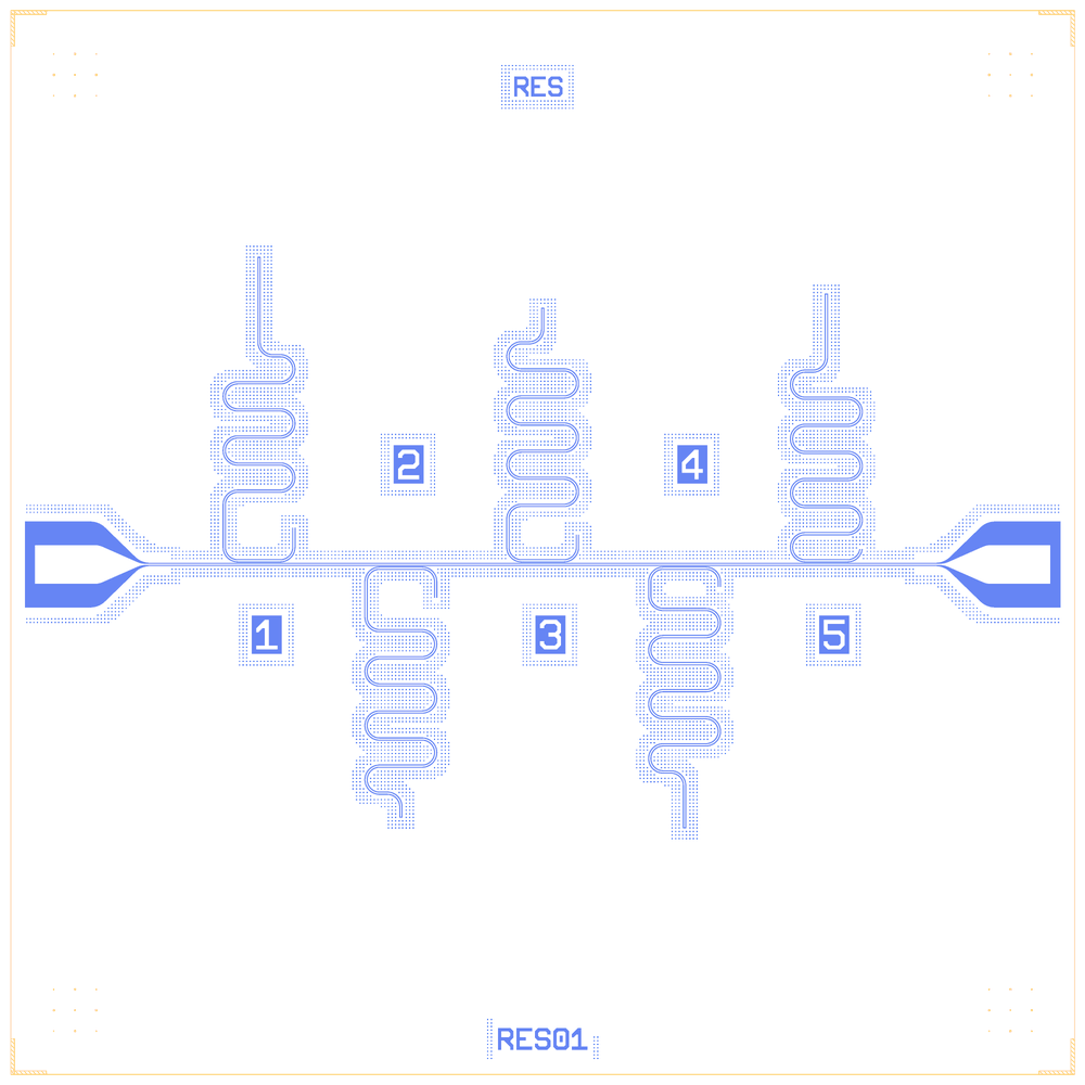
resonator_chip_01 as rebuilt on the Quantcore PDK
At a glance
Notebook |
|
Source script |
|
Chip |
7.5 × 7.5 mm die, 10/6 µm CPW |
On the chip |
5 λ/4 |
Builds today |
yes, rebuilt from its JSON on 2026-11-19 in 3.8 s (the notebook itself was not re-run) |
Pictures
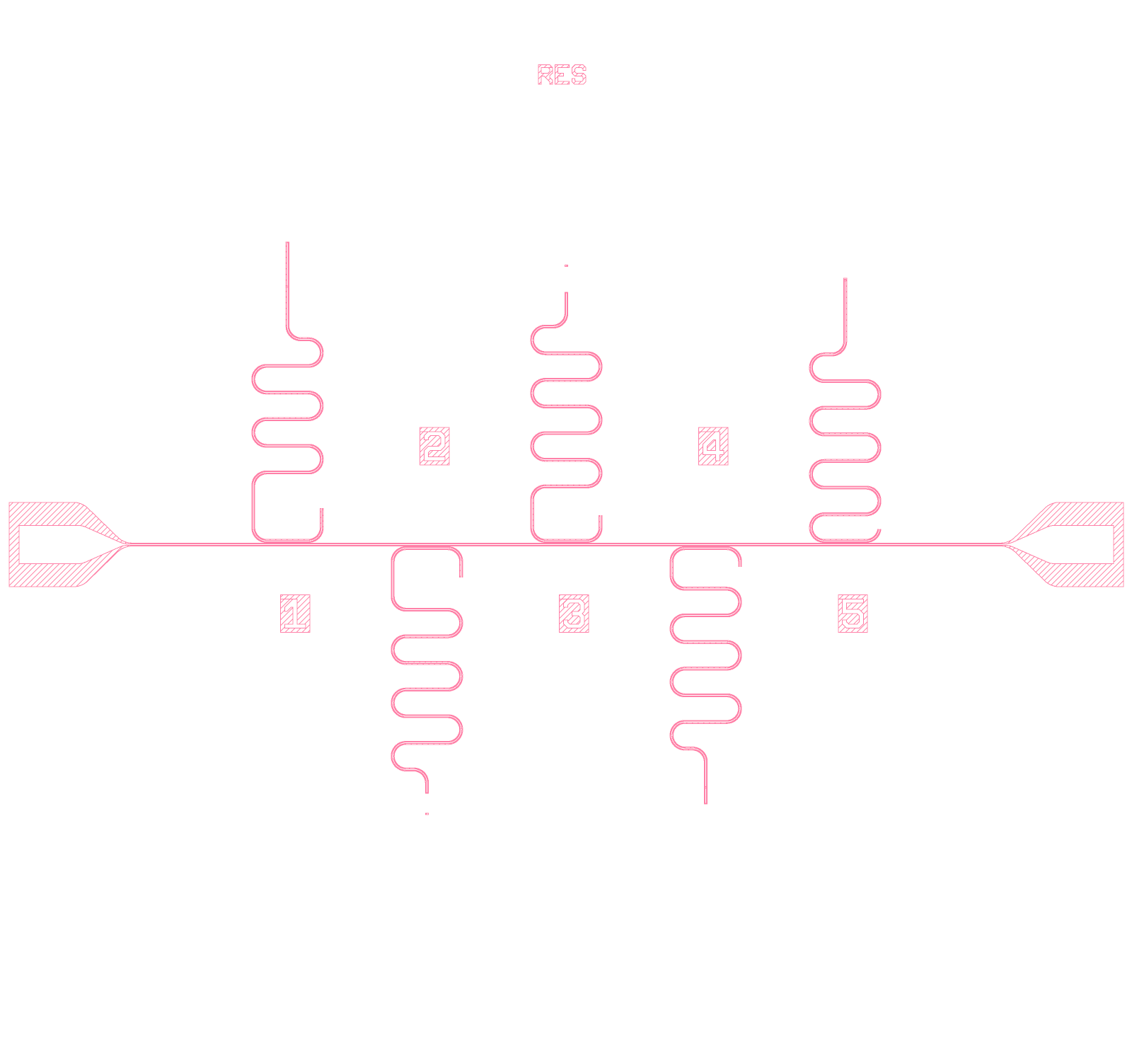
resonator_chip_01: the original legacy layout (render of the legacy GDS)
resonator_chip_01: the Quantcore rebuild
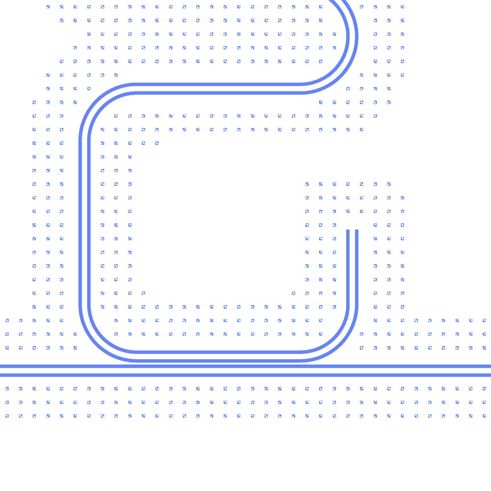
The first resonator where it runs along the feedline (the coupler) and its open end

A numbered label with its cheese keep-out
LOM estimates
The notebook’s saved outputs hold no LOM run (its LOM cells were not executed), so there are no estimates to show here and none were computed for this page. The build spec quotes about 6.37 GHz (loaded) for the five resonators from an earlier run.
Build spec
The rest of this page is the detailed spec the notebook was built from: components, positions, parameters and what changed from the legacy script.
Source: components/python/resonator_chip_01.py (create_chip, output res_01.gds), Quantcore internal.
Legacy PCells: Coplanar Waveguide, Connector Pad (connector_pad.lym), Coupled Resonator, Marker. (It
imports junction_creator, which is not in the library, but never calls it.) Rebuild:
examples/designs/legacy/resonator_chip_01.ipynb (+ .json, PNGs); tables and the legacy reference in
examples/designs/legacy/_legacy_b.py (RC1_*, resonator_chip01_reference).
Changes made in the rebuild
Grounder boxes: removed (not intended; the later PCell has dedicated open and short ends). Each resonator ends with its own gap cap (
ground=True), full 5000 µm, no floating stubs. All five now share one frequency (≈ 6.37 GHz loaded): degenerate on one feedline, so give different lengths if they should be spread.Pads: moved 345 µm inwards of the legacy tips (∓2975 → ∓2630, feedline 5950 → 5260 µm): the rounded pad end on the design-area edge, 100 µm inside the 7.5 mm die, clear of the dicing lane and corner markers.
The notebook’s JSON was rebuilt from its layout cell. The notebook has not been re-run, so its outputs are cleared and its PNGs may be out of date.
What it is: the resonator-only twin of chip_01 (docs/designs/legacy/chip_01.md): the same 5950 µm
feedline with lc/rc_thickness 2, the same two rounded Connector Pads and the same five Coupled Resonators
(cpw_len 5000, clength 300, cgap 2 µm, width 300, necks 600 / 550 / 500 / 400 / 300 µm), alternating above and below
at x = −2000 … 2000, with no Xmons. Instead, a 22 × 10 µm etched box (the “grounder”, the full CPW width) sits on or
beyond each resonator tail, at about the y where chip_01’s claw tails are (1850, 1930, 2000, 1740, 1895 µm vs
claw tips 1848, 1898, 1998, 1738, 1848). Labels “RES” and “1” … “5”. No frequency targets in the source.
Die: 7.5 × 7.5 mm, centred on (0, 0) → (+3750, +3750). PDK v2 die frame instead of the legacy Marker corners
and 10/0 boundary boxes.
Built; XOR 0.0 µm² against the legacy PCells on every resonator, grounder and label, and on the pads and feedline at the moved pad position (see below).
Components
instance |
legacy cell |
catalog ref |
key params |
at (x, y) µm |
rot |
legacy (x, y), notes |
|---|---|---|---|---|---|---|
|
|
|
length 5460 (legacy 5950), 10/6, lc/rc_thickness 2 |
(3750, 3750) |
0 |
(0, 0) |
|
|
|
pad 275 × 300, taper (conn_height) 300, trace 10/6, rounded |
(1020, 3750), snapped to |
270 |
legacy (−2975, 0) rot 3 → (−2730, 0) |
|
|
|
as PL |
(6480, 3750), snapped to |
90 |
(2975, 0) rot 1 → (2730, 0) |
|
|
|
neck 600 |
(1750, 3776) |
0, mirror |
(−2000, 26); tail end y = 2162.9 |
|
|
|
neck 550 |
(2750, 3724) |
0 |
(−1000, −26); end −1778.9 |
|
|
|
neck 500 |
(3750, 3776) |
0, mirror |
(0, 26); end 1803.9 |
|
|
|
neck 400 |
(4750, 3724) |
0 |
(1000, −26); end −1853.9 |
|
|
|
neck 300 |
(5750, 3776) |
0, mirror |
(2000, 26); end 1903.9 |
|
etched |
|
– |
legacy (−2000, 1850), (−1000, −1930), (0, 2000), (1000, −1740), (2000, 1895) + (3750, 3750) |
0 |
see “grounders” |
|
|
|
– |
(3550, 7050) |
0 |
(−200, 3300) |
|
|
|
inverted |
legacy (−2020, −600), (−1020, 600), (−20, −600), (980, 600), (1980, −600) |
0 |
resonator numbers |
– |
|
PDK die frame |
– |
– |
– |
replaced |
Resonator common (resParams_common): cpw_len 5000, clength 300, cgap 2, width 300, flip False, neck 500
(overridden), legacy defaults otherwise (gap 6, arc_length 300, ground True → shorted at the coupler, open tail).
Pads (deviation, forced): at the legacy tips (∓2975, 0) the rounded pads reach 245 µm past the die edge, which
the DRC reports as an error (outside_chip). As for chip_01 (same pads), both pads move 245 µm
inwards and the feedline shrinks to 5460 µm. The legacy script also leaves the pads’ sim at its default True
(pad metal + ground ring on 1/0, a simulation drawing); the rebuild uses the fab geometry (legacy bug not
reproduced).
Grounders: an etched box across the full CPW width cuts the trace. On R1, R4 and R5 it lies on the tail, so the resonator’s open end moves to the box and the rest of the tail is a floating stub; on R2 and R3 it lies beyond the tail end (just a hole in the ground plane):
resonator |
tail end y |
grounder y (±5) |
cut |
effective λ/4 length (µm) |
floating stub (µm) |
|---|---|---|---|---|---|
R1 |
2162.9 |
1850 |
yes |
4682.1 |
307.9 |
R2 |
−1778.9 |
−1930 |
no (146 µm past the end) |
5000 |
– |
R3 |
1803.9 |
2000 |
no (191 µm past) |
5000 |
– |
R4 |
−1853.9 |
−1740 |
yes |
4881.1 |
108.9 |
R5 |
1903.9 |
1895 |
yes |
4986.1 |
3.9 |
Routes
None (pads snap to the feedline; resonators couple by proximity).
LOM node structure
FL.line: feedline + both pads, 50 Ω at each pad.Each
Ri: λ/4TLres(drawn length 5000 µm) to ground + HANGER κ to the feedline (d.couple("K_Ri", "Ri", "FL"), 300 µm at 2 µm). The LOM does not see the grounder cut: the notebook corrects R1, R4, R5 by the effective length (table above).
Targets
None in the source.
Simplifications for a first rebuild
Pads moved inwards 245 µm (DRC error otherwise); pad
simgeometry not reproduced.PDK die frame instead of the legacy markers.