Nine-Xmon chip (chip_03)
A 7.5 mm die with ten quarter-wave resonators (4120 to 6790 µm, for 4.5 to 7.5 GHz) on one feedline, five above and
five below, and nine Xmon qubits on their ends; R7 is a bare resonator with no qubit. Eight arrays of small holes
between the resonators trap magnetic flux. It is Quantcore’s own Nb trilayer chip “for more qubits” (QWri legacy
script chip_03_trilayer.py, May 2024): a first multi-qubit chip to read many qubits out through one line.
The rebuild draws it from Quantcore PDK parts: resonator tails run into the Xmon claws, the bond pads sit 100 µm from the die edge, and the PDK frame is added. The PDK cheese (5 µm squares with 20 µm gaps, at least 4 µm from the 3/0 keep-outs) also covers the whole die, and the holes drawn in the original layout stay. Build this one to see how many resonators share a feedline and how the flux-trap hole arrays are placed.
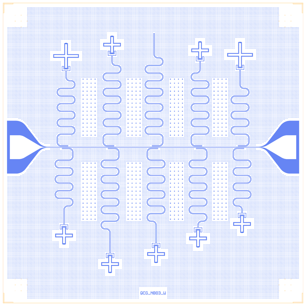
chip_03_trilayer as rebuilt on the Quantcore PDK
At a glance
Notebook |
|
Source script |
|
Chip |
7.5 × 7.5 mm die, 10/6 µm CPW, Nb trilayer junctions |
On the chip |
9 Xmons (two with 600 µm crosses) · 10 λ/4 resonators · 8 flux-trap hole arrays · 2 bond pads |
Builds today |
yes, rebuilt from its JSON on 2026-11-19 in 2.9 s (the notebook itself was not re-run) |
Pictures
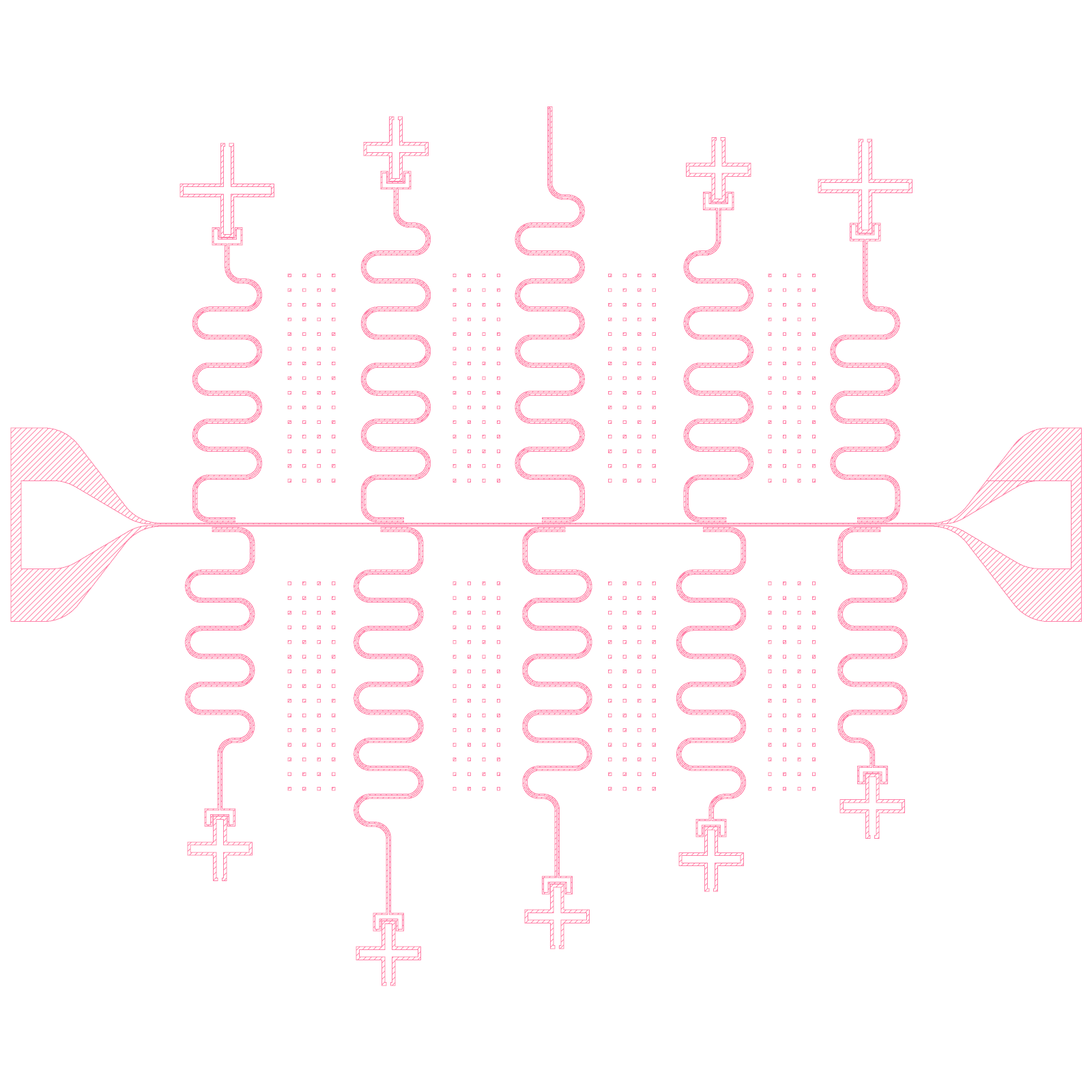
chip_03_trilayer: the original legacy layout (render of the legacy GDS)
chip_03_trilayer: the Quantcore rebuild
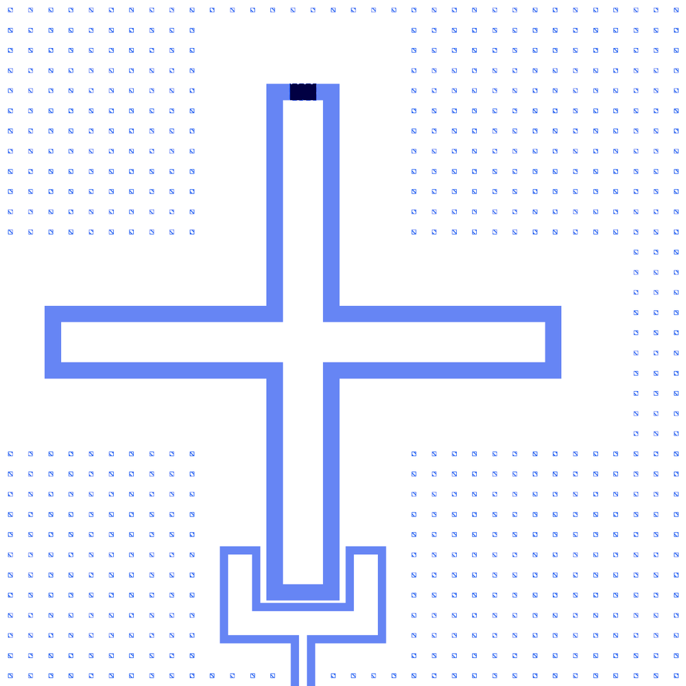
Q1, an Xmon with a 600 µm cross: the claw takes the resonator tail, the junction is at the north tip
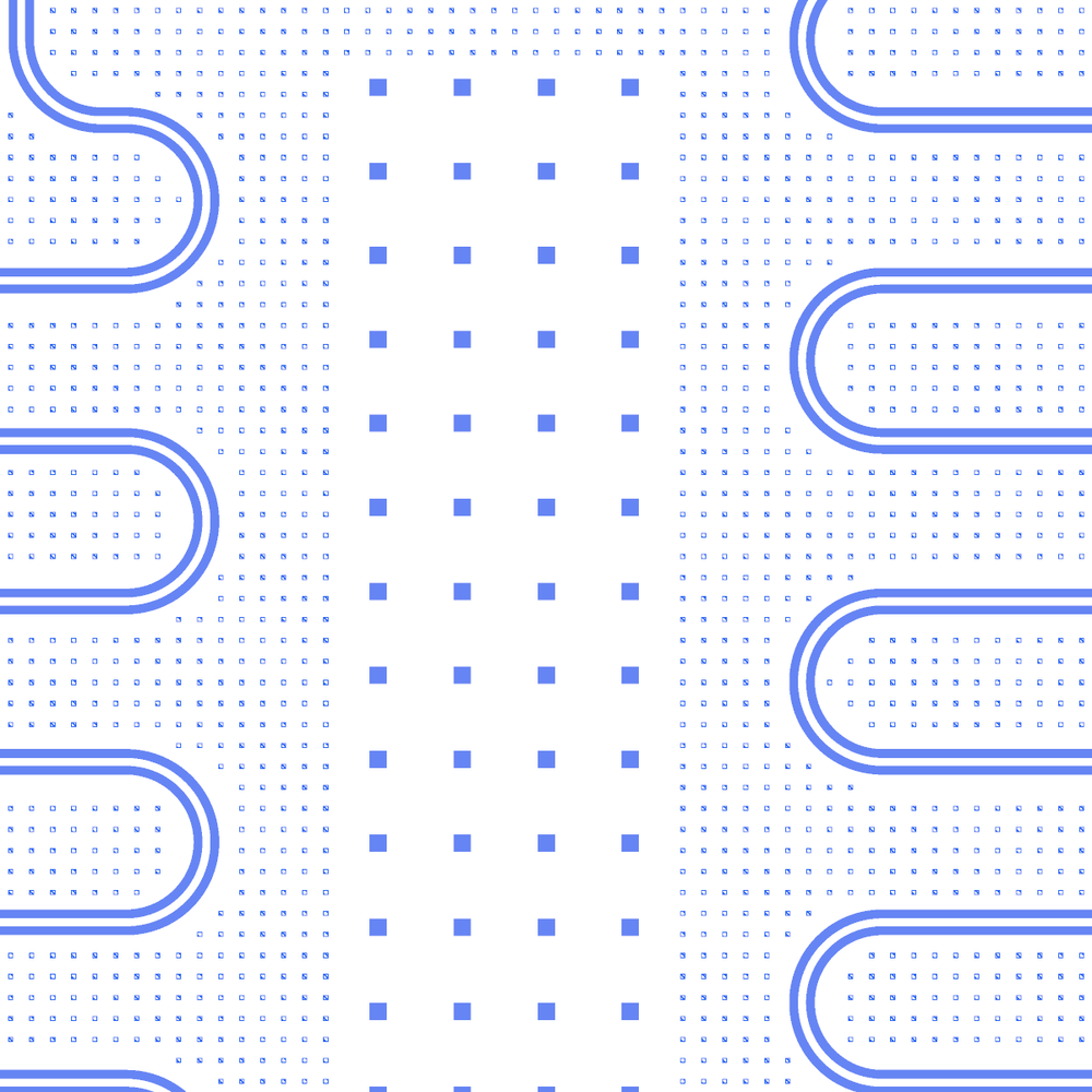
A flux-trap hole array between two resonators
R7, the resonator without a qubit: it ends in its own open end
LOM estimates
The notebook’s saved outputs hold no LOM run (its LOM cells were not executed), so there are no estimates to show here and none were computed for this page.
Build spec
The rest of this page is the detailed spec the notebook was built from: components, positions, parameters and what changed from the legacy script.
Source: components/python/chip_03_trilayer.py (create_chip(size), run as create_chip(5) from
__main__; May 2024; “Trilayer new design for more qubits, 12 resonators”). Legacy QWri
library, Quantcore internal. Notebook examples/designs/legacy/chip_03_trilayer.ipynb (size = 5).
Changes made in the rebuild
Claws, corrected: every qubit resonator now ends without a gap cap (
ground=False, the legacyCoupled Resonator’s “xmon connector” mode) and its Xmon is snapped with the claw-tail tip onto that end (snap="claw_n", to="Ri.end"): galvanic, the claw is the λ/4’s open end (as in chips 05/10a). Each Xmon keeps x and rotation and moves along the tail axis (table after the notebook’s layout cell).claw_tail_gap= legacycap_spacing(10 µm) viaL.xmon. As drawn seven tails ended 46–56 µm in with the end cap (floating claw) and R6/R8 ran 414 µm in, splitting Q6/Q8.R7, no cut: the full 6790 µm line with the PCell’s own open end (
ground=True); CUT7, the floating stubR7S,CAP7andW_R7removed. LOM R7 4.69 GHz (target 4.5).Junctions:
Trilayer Junction HSQnow drawn at the legacy fingers (js·0.1 × 0.5 µm,junction_params) and valued on the PDK junction rule (Nb trilayer, Δ = 1.4 meV, I_c·R_n = πΔ/2e = 2.20 mV, R_n 40–50 kΩ, qubits 4–8 GHz; PDK processget_pdk().junction: R_n·A 13.5 kΩ·µm², C_J 50 fF/µm², both assumed by the PDK): js 5 → 54 kΩ, js 8 → 33.75 kΩ. LOM: f_q 4.5–6.6 GHz; Q9/R9 and Q10/R10 hybridised.FEM: the C-matrix groups no longer have a separate claw net (claw and resonator are one conductor) (
tests/test_sim_tools.py::test_floating_claw_is_named_by_proximityneeds its expectation updated).The notebook’s JSON was rebuilt from its layout cell. The notebook has not been re-run, so its outputs are cleared and its PNGs may be out of date.
What it is: a 7.5 × 7.5 mm die centred on (0, 0) → Designer (x + 3750, y + 3750), PDK v2 die frame (replaces
the four corner Markers, rot 1/2/3/0, and the layer-10 outline / 500 µm boxes, which the script clears at the
end anyway). One horizontal feedline between two rounded connector pads; ten Coupled Resonator λ/4 meanders at
|y| = 33 µm from it (R3/R4 commented out of the source, so numbering skips them), five above and five below at
x = −2200, −1050, 50, 1150, 2200; nine Xmon Cross qubits at the resonator tails (R7 has none: its Xmon is
commented out); eight 4 × 15 flux-trap hole arrays between the resonators; one etched box cutting R7’s tail. No
test pads (commented out). Labels “TOP=500nm” and “QCG_Nb03_W”.
Builds: yes. All cells ported, with LOM models. Not drawn: junction windows (CLEARER; Xmon.junction_window=[30, 27, -3]
exists now, not yet applied here) and text labels; junction_creator.py (imported as jc) is not in the library; its create_junction(js, secondFinger, path) signature and JUNC_<js> cell match junction_creator_HSQ.py, so the closest port
TrilayerJunctionHSQ is used.
Components (legacy frame, µm)
instance |
legacy cell → catalog ref |
params |
at (x, y) |
rot / mirror |
|---|---|---|---|---|
FL |
Coplanar Waveguide → |
length 7500 − 2000 − 40 = 5460 → 5360 (see pads), a/b 10/6, lc/rc 2 |
(0, 0) |
0 |
PL, PR |
Connector Pad → |
pad 600 × 200, taper (conn_height) 500, trace 10/6, round True, sim False |
(∓2680, 0) = ∓(3750 − 1000 − 70) |
270° / 90° |
R1, R2, R5, R6, R7, R8, R9, R10, R11, R12 |
Coupled Resonator → |
common: gap (b) 10, clength 200, cgap 7, width 250, neck 400, ground True; cpw_len 4740 / 4410 / 5840 / 6200 / 6790 / 5590 / 5340 / 5200 / 4410 / 4120; flip True for R2, R6, R7, R10, R11 |
(−2200, ±33), (−1050, ±33), (50, ±33), (1150, ±33), (2200, ±33) (odd = +33) |
mirror True above, False below |
Q1, Q11 |
Xmon Cross → |
width 600 → cross_length, thickness 50 → arm_width, spacing 20 → gap, da 3, cap_spacing 10, pthickness 30, fwidth 30, ggap 15, handle 1 |
(−2175, 2225), (2175, 2254) |
180° |
Q2, Q5, Q6, Q8, Q9, Q10, Q12 |
Xmon Cross → |
as above with width 400 |
(−2225, −2157), (−1025, 2507), (−1075, −2508), (75, −2257), (1175, 2375), (1125, −2225), (2225, −1864) |
180° above / 0° below |
junctions |
|
js (bot) = 8, 5, 8, 5, 8, 5, 5, 5, 5 → straight finger 0.8 / 0.5 µm; second finger 0.5·5/5 = 0.5 µm |
(x_q, y_q ± (cross/2 + 10)) |
mirror below the feedline |
CLEARER |
30 × 27 µm cut from 1/0 and 3/0, centred 7 µm beyond the cross tip (a source comment says it was added on request) |
MISSING (Xmon keeps its 30 × 20 gap etched) |
||
H0N … H3S |
|
|
(x + 450, 300) and (x + 450, −1800) for x = −2200, −1075, −15, 1075 |
0 |
CUT7 |
|
|
(25, 2467.33) |
90° |
R7 as built |
the 6790 µm cell minus CUT7 = R7 open at the cut + a floating stub |
R7 drawn to the cut: |
R7S (25, 2484.5), CAP7 (25, 2839.832) |
90° |
labels |
“TOP=500nm” (1500, 3200), “QCG_Nb03_W” (1800, −3200), 200 µm |
MISSING (text cell); |
Pads and feedline: the legacy feedline (±2730) overlaps the pad tips (±2680) by 50 µm of identical 10/6 CPW (the rounded pad ends in a 200 µm CPW stub). The rebuild snaps the pads to a 5360 µm feedline: the same etch (XOR 0), and the rounded pads end exactly at the die edge.
Resonator tail ↔ claw (as drawn)
The legacy design places every Xmon so that its resonator’s open tail (with its gap cap) ends inside the claw tail: the claws are floating metal islands (checked on the rebuilt metal), coupled to the tail end capacitively.
pair |
tail past the claw tip (µm) |
G (rough, fF) |
note |
|---|---|---|---|
Q1, Q5, Q10, Q11, Q12 |
54.9 / 54.8 / 55.9 / 54.9 / 54.9 |
1.4–1.5 |
end cap 5 µm into the claw base |
Q2, Q9 |
51.9 / 45.9 |
1.0 / 0.8 |
|
Q6, Q8 |
413.8 / 413.9 |
47 |
the tail runs through the claw (split in two) and the cross arm to 100 µm past the cross centre |
R7 has no qubit; CUT7 cuts its centre conductor at y = 2467.33–2484.5, on the straight tail 372.5 µm before the
end cap (y = 2839.832). What the mask leaves: a λ/4 of 6417.5 µm from the shorted coupler end, open at the cut, and
beyond the cut a floating 355.3 µm piece of 10/10 µm line with R7’s end cap. The rebuild draws exactly that (R7 to
the cut, CUT7, R7S, CAP7): etch XOR 0.0 µm² against the legacy R7 + CUT7. LOM: R7 λ/4
6417 µm, 4.968 GHz bare, 4.959 GHz on the feedline (the uncut 6790 µm gave 4.696 / 4.687 GHz; source comment 4.5
GHz). The stub couples to R7’s open end only across the 17 µm cut (≪ 1 fF): neglected. The cut retunes R7 by ≈ +0.27 GHz and leaves a floating island; whether the cut is intended, or R7 was meant uncut, is not confirmed.
LOM node structure
FL.line (50 Ω at each pad) ─ HANGER κ (K_Ri: 200 µm coupler, 7 µm ground strip) ─ Ri.res (λ/4 TLres,
shorted at the coupler) ─ C G_Qi ─ Qi.claw_n ─ C_g ─ Qi island (C, trilayer JJ to ground). R7: R7.res
(λ/4 to the cut, open at CUT7 via W_R7) ─ HANGER ─ FL.line. Flux-hole arrays, R7S and CAP7 have no circuit
role (ground holes; floating stub; its cap’s port maps to ground).
Targets
The source comments resonator frequencies: R1 6.5, R2 7, R5 5.25, R6 5, R7 4.5, R8 5.5, R9 5.75, R10 6, R11 7,
R12 7.5 GHz (res1p … res12p). No qubit targets.
Simplifications
CLEARER windows and labels not drawn; junction geometry = Trilayer Junction HSQ at its default fingers (the
Xmon cannot pass finger widths yet), the js sweep goes into the LOM L_J (assumed Jc). The G couplings are rough
estimates for the FEM to replace.