QualityFactor (KQC)
A resonator-Q test chip from KQCircuits: six quarter-wave resonators of different widths and coupler types hang on one feedline. There are no qubits. You measure each resonator’s frequency and quality factor. A flip-chip version is in the test chips (quality_factor_twoface).
Build it to see how resonator elements that carry their own probe-line stub are chained into a feedline.
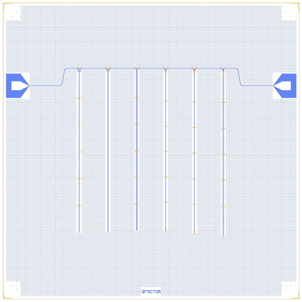
At a glance
Notebook |
|
Source |
KQCircuits |
Chip |
10 × 10 mm, SMA8 launchers (west in, east out), chip name “QFACTOR” |
On the chip |
6 λ/4 resonators (5374 to 5589 µm) · 1 feedline · no qubits |
Builds today |
yes (layout built on 2026-11-19 in 6 s) |
How the notebook builds it
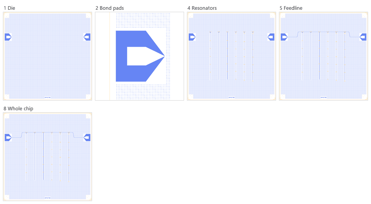
Die. The empty 10 × 10 mm chip with the Quantcore frame (dicing marks, alignment grids, chip boundary, device ID) and the two launchers.
Bond pads. The launchers moved so their outer etch edge sits 100 µm from the die edge (the pad rule).
Resonators. Six KQC
QuarterWaveCpwResonators, each with its own coupler and a stub of the feedline.Feedline. Seven CPW routes join the launchers and the six stubs.
Whole chip. One sim group per resonator, centring check, design saved. (Designs 3, 6 and 7 have nothing to place.)
LOM estimates
Numbers are from a run of this notebook on 2026-11-19 (Setup, Design, Check and the LOM cells, 14 s): QuCat normal modes with QuTiP dressed values.
mode |
kind |
f (GHz) |
κ (MHz) |
A (MHz) |
participation |
|---|---|---|---|---|---|
R5 |
resonator |
5.627 |
0.0652 |
0 |
R5 1.00 |
R0 |
resonator |
5.715 |
1.49 |
0 |
R0 1.00 |
R4 |
resonator |
5.718 |
0.116 |
0 |
R4 1.00 |
R1 |
resonator |
5.749 |
0.74 |
0 |
R1 1.00 |
R3 |
resonator |
5.795 |
0.133 |
0 |
R3 1.00 |
R2 |
resonator |
5.838 |
0.23 |
0 |
R2 1.00 |
mode |
f_r (GHz) |
κ (MHz) |
Q_ext = f_r / κ |
|---|---|---|---|
R5 |
5.627 |
0.0652 |
86,253 |
R0 |
5.715 |
1.49 |
3,848 |
R4 |
5.718 |
0.116 |
49,370 |
R1 |
5.749 |
0.74 |
7,769 |
R3 |
5.795 |
0.133 |
43,557 |
R2 |
5.838 |
0.23 |
25,423 |
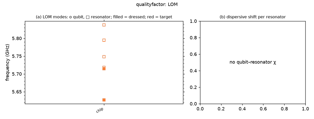
These are lumped-model estimates (component formulas and calibration), not FEM results; see the LOM page for how far to trust them.
Build spec
The rest of this page is the detailed spec the notebook was built from: every component, port, route and length.
Sources other-libs/KQCircuits-main/KQCircuits-main/klayout_package/python/kqcircuits/chips/quality_factor.py
(QualityFactor) and .../chips/quality_factor_twoface.py (QualityFactorTwoface), GPL-3.0 (IQM Finland).
Rebuilt from extracted parameters. What it is: resonator-Q test chips. One feedline carries 6 capacitively coupled
λ/4 CPW resonators of different widths and coupler types. There are no qubits. 10 × 10 mm (box is a parameter),
KQC frame = Designer frame. QualityFactor: lengths match KQC and the LOM gives 6 λ/4 (checked on 2026-11-02).
QualityFactorTwoface needs DPath poly_path/input_path parameters for SpiralResonatorPolygon (see
below).
Components
QualityFactor: 6 × QuarterWaveCpwResonator, rot 0, at (2500 + 1000·i, 7794.5) for i = 0…5. The feedline height is
(10000 + max(res_lengths)) / 2 = 7794.5 and the resonators hang down. Shared: probeline_length=120, max_res_len=5589, tl_airbridges=True, ground_grid_in_trace=0. Ports: a (x−60, 7794.5), b (x+60, 7794.5), resonator_b at the far end
(unused).
instance |
resonator_length |
res_a / res_b |
type_coupler |
n_fingers |
l_fingers |
res_beg = res_term |
n_ab |
|---|---|---|---|---|---|---|---|
R0 |
5434 |
5 / 3 |
interdigital |
4 |
23.1 |
galvanic |
5 |
R1 |
5429 |
10 / 6 |
interdigital |
4 |
9.9 |
galvanic |
0 |
R2 |
5374 |
20 / 12 |
interdigital |
2 |
14.1 |
galvanic |
5 |
R3 |
5412 |
5 / 3 |
gap |
4 |
10 |
airbridge |
5 |
R4 |
5493 |
10 / 6 |
gap |
4 |
21 |
airbridge |
5 |
R5 |
5589 |
20 / 12 |
gap |
4 |
28 |
airbridge |
5 |
Routes
route |
from → to |
type, length (µm) |
waypoints |
notes |
|---|---|---|---|---|
PL0 |
chip.PL-1-IN → R0.a |
cpw 2085.35 |
(1900,7200), (2000,7794.5) |
slanted 100 µm bend ( |
PL1–PL5 |
R(i).b → R(i+1).a |
cpw 880 each |
none |
|
PL6 |
R5.b → chip.PL-1-OUT |
cpw 2085.35 |
(8000,7794.5), (8100,7200) |
d = Designer("kqc_quality_factor", launchers={"type": "SMA8", "assign": {8: "PL-1-IN", 3: "PL-1-OUT"}})
L, NF, LF = [5434, 5429, 5374, 5412, 5493, 5589], [4, 4, 2, 4, 4, 4], [23.1, 9.9, 14.1, 10, 21, 28]
RA, RB, NAB = [5, 10, 20, 5, 10, 20], [3, 6, 12, 3, 6, 12], [5, 0, 5, 5, 5, 5]
TC, TERM = ["interdigital"] * 3 + ["gap"] * 3, ["galvanic"] * 3 + ["airbridge"] * 3
for i in range(6):
    d.add(f"R{i}", "QuarterWaveCpwResonator", at=(2500 + 1000 * i, 7794.5), probeline_length=120.0, max_res_len=5589.0,
          resonator_length=L[i], res_a=RA[i], res_b=RB[i], type_coupler=TC[i], n_fingers=NF[i], l_fingers=LF[i],
          res_beg=TERM[i], res_term=TERM[i], n_ab=NAB[i], tl_airbridges=True)
d.route("PL0", "chip.PL-1-IN", "R0.a", nodes=[(1900, 7200), (2000, 7794.5)])
for i in range(5):
    d.route(f"PL{i + 1}", f"R{i}.b", f"R{i + 1}.a")
d.route("PL6", "R5.b", "chip.PL-1-OUT", nodes=[(8000, 7794.5), (8100, 7200)])
QualityFactorTwoface (same file)
frames_enabled=[0,1], SMA8 with the same names. Everything sits on face 1t1 with defaults
(resonator_faces=[0,1], all “capped”). The probeline uses the capped CPW a_capped=10, b_capped=10.
Probeline: chip.PL-1-IN (800,7200) → taper at (1500,7200) to a=10 b=10 (
waypoint(a=10, b=10, taper_length=100)) → (2000,7200) → (2000,5000) → (2300,5000) → 6 T’s → (7700,5000) → (8000,5000) → (8000,7200) → taper back to a=10 b=6 at (8400,7200) → chip.PL-1-OUT. Build the T’s asWaveguideCoplanarSplitterinstances (angles=[0,180,90 / 270]alternating,lengths=[15,15,65]) at x = 3208.33, 4025, 4841.67, 5658.33, 6475, 7291.67, y = 5000. Port c faces down for even i and up for odd i. Connect them with route segments; KQC uses inline splitter nodes, which Designer has no waypoint for.Coupler k:
FingerCapacitorSquarewithcap_params(n_fingers, l_fingers, type),b=10, a2=res_a, b2=res_b, snapa→ T_k.c. Its port b is at (x, 4856.9 / 5129.9 / 4865.9 / 5115 / 4874 / 5133).Resonator k:
SpiralResonatorPolygon(length=res_lengths[k], a=res_a, b=res_b, bridge_spacing=0, input_path=DPath[(0,0)] w10, poly_path=DPath[(200,0),(2000,0),(2000,-500),(200,-500)] w10)at Ck.b, rot 270 (even k) or 90 with mirror (odd k). Here res_a = [10,10,10,20,10,5] and res_b = [6,6,6,12,6,3]. Blocked: Designer/design.jsoncannot carry DPath params (tested: the PCell gets a str). Workarounds: use the spiral defaults (triangle path), or replace each spiral withd.route(f"RS{k}", Ck.b, Designer.free_end(..., term=0), meander=L_k).
Launchers, pads, test structures, markers, labels
SMA8 named launchers: PL-1-IN = pad 8 (800,7200), PL-1-OUT = pad 3 (9200,7200). KQC pad_pitch = chip_side − 5600
equals the default 4400 for 10 mm. No other structures.
LOM node structure (qubit ↔ resonator ↔ feedline ↔ bus ↔ control lines)
Feedline node (all R*.pl merged) with 50 Ω ports PL-1-IN/OUT. Each resonator: Ck_Ri from the feedline to Ri.res,
then a λ/4 TLres. Tested lumped values (sapphire PDK): f = 5.96 / 5.90 / 5.92 / 5.99 / 5.83 / 5.69 GHz and Ck ≈ 10.8 /
7.5 / 4.1 / 3.1 / 2.5 / 2.3 fF (estimates). Ri.resonator_b stays unconnected, which is fine (open far end).
Targets (if stated)
None beyond the parameters. The QualityFactor docstrings call res_lengths “physical length” and the couplers
“planar capacitors”.
Simplifications for a first rebuild
QualityFactor suits λ/4 + κ calibration (resonators only, no qubits), so build it as is. For QualityFactorTwoface, wait for TypeShape param support or use the meander-route replacement above.
Quantcore PDK rebuild
The notebook is a Quantcore-PDK rebuild of the source chip. The netlist, LOM and imported components are kept, and the process is Quantcore’s.
Notebook: examples/designs/kqc/qualityfactor.ipynb.
Chip: the Quantcore die frame (L dicing markers 1000/0, 3 × 3 alignment grids 1001/0, chip boundary 100/0, device ID where an edge is free; any brand text is QCT), drawn on the source’s 10 × 10 mm chip (its launchers sit on the chip edges, so the design does not fit the 7.5 mm die). KQC’s ChipFrame (dicing edge, corner markers, labels) is not drawn. KQC’s original grids its whole ground plane (
with_grid, 5 µm squares on a 10 µm step). The rebuild keeps that coverage at the PDK density instead (chip parametercheese: "chip",with_grid: false): 5 µm squares with 20 µm gaps over the whole die, at least 4 µm from the 3/0 keep-outs, inside the design area and clear of the frame markers and the device ID.Stack: sapphire 650 µm, εr 10.25 (the PDK default stack, used by the LOM estimates and every FEM export); KQC’s own simulation default is silicon (εr 11.45), so LOM capacitances and resonator frequencies here are for sapphire.
Junctions: none on this chip (no qubits or junctions).
Kept: the topology and every KQC element with the source’s parameters, positions and orientations, the launcher assignment, every route’s path and length, the sim groups (resonator lengths 5374–5589 µm, coupler types, airbridges).