SpiralResonatorPolygon
The PCell declaration for a polygon shaped spiral resonator.
Source: KQC (KQCircuits). Category: resonator. Module: kqcircuits.elements.spiral_resonator_polygon.
See also the catalog.
Pins
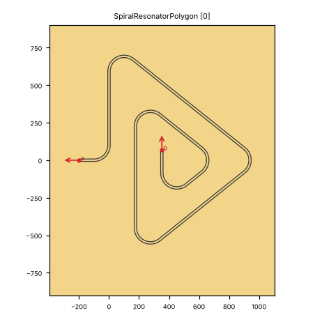
Pin image (default parameters). Light = metal, dark = etched gap, colours = junction layers. A red dot and arrow is a pin and its direction (out of the cell); the red bar is the CPW width a + 2 b. Blue dot = a pin without direction. Units: µm.
pin |
x (µm) |
y (µm) |
direction (°) |
a (µm) |
b (µm) |
purpose |
|---|---|---|---|---|---|---|
|
-200 |
0 |
180 |
10 |
6 |
CPW end; LOM node |
|
352.228 |
67.13 |
90 |
10 |
6 |
CPW end; LOM node |
a, b: CPW centre width and gap where the pin declares them (– = not declared). Position and direction are in the cell’s own frame (at=(0, 0), rot=0).
Parameters
name |
default |
unit |
description |
|---|---|---|---|
|
|
μm |
Width of center conductor |
|
|
μm |
Width of gap |
|
|
μm |
Turn radius |
|
|
μm |
Resonator length |
|
|
– |
Use automatic spacing |
|
|
– |
Include connector length |
|
|
[μm] |
Manual spacing pattern |
|
|
μm |
Airbridge spacing |
|
|
μm |
Termination length start |
|
|
μm |
Termination length end |
|
|
μm |
Bridge width |
|
|
μm |
Pad length |
|
|
μm |
Bridge length (from pad to pad) |
|
|
– |
Pattern for number of airbridges on edges |
|
|
µm |
Face to face connector distance from beginning |
|
|
μm |
Conductor width at the connector area |
|
|
μm |
Gap width at the connector area |
|
|
– |
Use round connector shape |
|
|
– |
Airbridge type |
|
|
– |
Include bumps |
|
|
μm |
Under-bump metalization diameter |
|
|
μm |
Bump diameter |
|
|
– |
Bump type |
Electrically relevant parameters (sizes, gaps, junction, ports) come first, the rest follows.
LOM model
The cell contributes to the lumped model:
no lumped branches
line |
node |
length (µm) |
a (µm) |
b (µm) |
ends |
|---|---|---|---|---|---|
|
|
5000 |
10 |
6 |
short / short |
Nodes: res.
Simulation export notes
C7: C-matrix nets without a design label (warning) (status: fixed; fix in sim_tools/builder.py (_cell_probes, label_unnamed); layouts/others/amplifiers.py (JtwpaChain.qcc_probes))
How to use
In Python:
from quantcore_circuits.designer import Designer

d = Designer("demo", box=(0, 0, 7500, 7500))
d.add("U1", "SpiralResonatorPolygon", at=(3750, 3750), a=10)   # parameters: see the table above
d.add("PAD", "BondPad", at=(1125, 3750), rot=270)   # a launcher to connect to
d.route("L1", "PAD.a", "U1.a")                # a CPW from the pad to the pin
Pin names go into d.route(...) as INSTANCE.pin, and into snap= / to= when placing. From the shell: qcc components SpiralResonatorPolygon lists the pins; add --schema for the parameters.
In KLayout: Quantcore panel ▸ Components ▸ double-click the cell, then click on the layout to place it. Rotate and mirror before the click; use Connect on two pins to route.