SuperInductor
The PCell declaration for a Manhattan style single junction.
Source: KQC (KQCircuits). Category: junction. Module: kqcircuits.junctions.super_inductor.
See also the catalog.
Pins
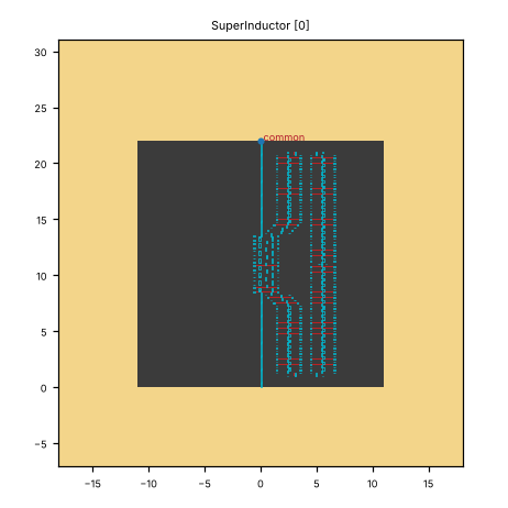
Pin image (default parameters). Light = metal, dark = etched gap, colours = junction layers. A red dot and arrow is a pin and its direction (out of the cell); the red bar is the CPW width a + 2 b. Blue dot = a pin without direction. Units: µm.
pin |
x (µm) |
y (µm) |
direction (°) |
a (µm) |
b (µm) |
purpose |
|---|---|---|---|---|---|---|
|
0 |
22 |
none |
10 |
6 |
junction lead (the LOM’s L_J branch); LOM node |
Pins with direction none: common. They mark a point (a junction lead, a pad centre), not a CPW end. The KLayout ghost draws them as boxes. A route can start there only where the notes say so; it cannot be snapped to.
a, b: CPW centre width and gap where the pin declares them (– = not declared). Position and direction are in the cell’s own frame (at=(0, 0), rot=0).
Parameters
name |
default |
unit |
description |
|---|---|---|---|
|
|
μm |
Width of center conductor |
|
|
μm |
Width of gap |
|
|
μm |
Turn radius |
|
|
– |
Junction Type |
|
|
μm |
Junction width for code generated element |
|
|
μm |
Junction length |
|
|
μm |
Wire width |
|
|
μm |
Phase slip junction length |
|
|
μm |
Width of Squids Area. |
|
|
μm |
Height of Squids Area. |
|
|
– |
Number of Squids in the Super Inductor. |
|
|
μm |
Length of the wire between SQUIDs. |
|
|
μm |
Length of the horizontal connector between the corner of the junction to the wire of the squid. |
|
|
μm |
Vertical margin from bends to limit of the circuit |
|
|
μm |
Horizontal displacement of the taper from the junction. |
|
|
μm |
Horizontal displacement step of the taper from the junction. |
|
|
– |
Relative width of bend according to junction_width |
|
|
μm |
Width of the shadow layer. |
|
|
– |
Include base metal gap layer. |
|
|
μm |
Length of fingers inside the pads. |
|
|
μm |
Height of the junction element. |
|
|
μm |
Width of the junction element. |
|
|
μm |
Minimum height of the shadow layer. |
|
|
– |
Include base metal addition layer. |
|
|
μm |
Shadow layer margin near the the pads. |
Electrically relevant parameters (sizes, gaps, junction, ports) come first, the rest follows.
LOM model
The cell contributes to the lumped model:
branch |
type |
nodes |
value (estimate at defaults) |
|---|---|---|---|
|
JJ |
j – gnd |
Lj_nH=–, Cj_fF=0 |
Nodes: j.
Simulation export notes
C3: junction sub-cell simulated on its own (status: fixed; fix in sim_tools/builder.py (is_junction_cell, _is_qubit, build_simulation); sim_tools/subset.py (has_junction))
How to use
In Python:
from quantcore_circuits.designer import Designer

d = Designer("demo", box=(0, 0, 7500, 7500))
d.add("U1", "SuperInductor", at=(3750, 3750), a=10)   # parameters: see the table above
# no directed pin: place it with at= / rot=, or snap it with snap= / to=
Pin names go into d.route(...) as INSTANCE.pin, and into snap= / to= when placing. From the shell: qcc components SuperInductor lists the pins; add --schema for the parameters.
In KLayout: Quantcore panel ▸ Components ▸ double-click the cell, then click on the layout to place it. Rotate and mirror before the click; use Connect on two pins to route.