Near-ms transmon sample (Tuokkola)
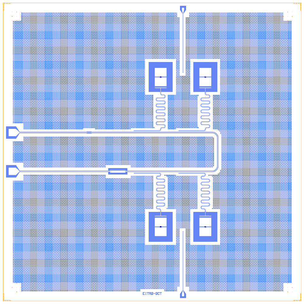
The sample of Tuokkola et al. (Aalto University and VTT), whose transmons reach near-millisecond coherence times: four transmons, each read out by a λ/4 hanger on a shared Purcell filter between two capacitors, with two drive lines. The data and fab GDS are on Zenodo (CC BY 4.0); the notebook is a Quantcore PDK rebuild (GPL-3.0) from the local Zenodo files and keeps the original chip as a reference file.
This notebook is an example of junctions sized from measured qubit frequencies, a Purcell filter in front of the readouts, and a rebuild checked against a reference layout.
At a glance
Notebook |
|
Source |
Zenodo record 14651787 ( |
Chip |
10 × 10 mm Quantcore die (the sample’s size) |
On the chip |
4 launchpads · 4 pocket transmons · 2 filter capacitors and the Purcell filter · 4 λ/4 hanger readouts · 2 feed lines · 2 drive lines |
Builds today |
yes (layout built on 2026-11-19 in 15 s) |
How the notebook builds it
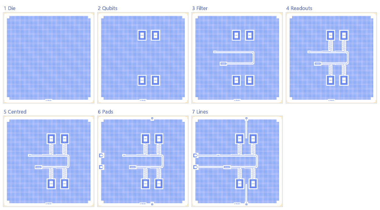
Die. The 10 × 10 mm die with the frame and the device ID
EITR2-QCT.Qubits. Four pocket transmons, junctions sized for the measured frequencies.
Filter. The Purcell filter between its two capacitors.
Readouts. Four λ/4 hangers on the filter.
Centre. The circuit is centred in the die before the pads.
Bond pads. Four launchpads on the 100 µm pad rule.
Lines. The feed lines and the two drive lines.
Whole chip. Sim groups, targets, save.
LOM estimates
Numbers are from a run of this notebook on 2026-11-19 (Setup, Design, Check and the LOM cells, 20 s): QuCat normal modes with QuTiP dressed values.
group |
qubit |
f_q (GHz) |
α (MHz) |
resonator |
f_r (GHz) |
κ (MHz) |
χ (MHz) |
|---|---|---|---|---|---|---|---|
Q1R |
Q1 |
4.023 |
-214 |
R_Q1 |
5.845 |
0.00918 |
-3.05 |
Q2R |
Q2 |
2.83 |
-241 |
R_Q2 |
5.957 |
0.00973 |
-1.36 |
Q3R |
Q3 |
4.483 |
-206 |
R_Q3 |
6.082 |
0.0102 |
-4.21 |
Q4R |
Q4 |
3.284 |
-230 |
R_Q4 |
6.192 |
0.0108 |
-1.56 |
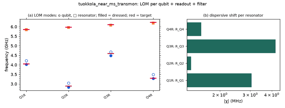
These are lumped-model estimates (component formulas and calibration), not FEM results. The LOM page says how far to trust them.
Build spec
The rest of this page is the detailed spec the notebook was built from, with every component, port, route and length.
The notebook
examples/designs/community/tuokkola_near_ms_transmon.ipynb(with its.jsonand PNGs) is a Quantcore PDK rebuild from the local Zenodo files incomponents/Zenodo_files/. The reference chip isexamples/designs/community/tuokkola_near_ms_transmon_sample.oas.
Source: zenodo.org/records/14651787, Data and GDS file for “Methods to achieve near-millisecond energy relaxation and dephasing times for a superconducting transmon qubit”. The authors are M. Tuokkola, Y. Sunada, H. Kivijärvi, J. Albanese, L. Grönberg, J.-P. Kaikkonen, V. Vesterinen, J. Govenius and M. Möttönen (Aalto University and VTT). The record was published 2025-01-15, v4, licence CC BY 4.0.
Local copy: components/Zenodo_files/Zenodo_files/:
README.txt: T1/T2echo data layout only, no device parameters;sample.gds: the measured chipEITR2, 10 × 10 mm, centred on (0, 0);Supplementary_material/Sample_design.gds: the 30 × 35 mm wafer layout, cellschip0…chip19of 5 × 5 mm each;Supplementary_material/: also the sample-holder cavity STEP/PDF files and RO/T1 data;data/Cooldown1|2/Q1–Q4_results: T1/T2echo IQ traces.
Chip read from sample.gds (EITR2; µm, source centred on (0, 0), Designer = source + (5000, 5000))
Read with klayout.db: 39 232 base-metal gap polygons on layer 130/1 and junction layers 8/0 and 8/1. The layers were
copied into tuokkola_near_ms_transmon_sample.oas.
element |
geometry |
|---|---|
qubits Q1–Q4 |
floating two-pad transmons. Pocket 800 × 1000, pads 400 × 300, pad gap 20, coupler bar 400 × 20 at 40 µm from the pad with an 11/5 µm lead. Centres (−100, 2513), (1400, 2513), (1400, −2513), (−100, −2513); Q3/Q4 rotated 180°. Q1 and Q3 have SQUIDs, Q2 and Q4 single junctions (junction layers 8/0, 8/1) |
Purcell filter |
U-shaped λ/2 CPW 21/11 µm. Top run y = +650, bottom run y = −650, U at x = +1816. Input finger capacitor (2 fingers, 100 µm) at the top left, output interdigital capacitor (7 fingers, 500 µm) at the bottom left |
readouts |
four λ/4s (CPW 11/5 µm), each from a qubit’s coupler bar, meandered, with 900 µm coupled to the filter across a 31 µm ground strip, shorted |
drive lines |
two, each shared by a qubit pair (Q1 + Q2 top, Q3 + Q4 bottom), open 5 µm ends between the pockets |
launchers |
2 filter ports on the left edge (y = ±650), 2 drive ports at the top and bottom |
other |
chip labels |
Targets: qubit frequencies 4.047 / 2.890 / 4.593 / 3.295 GHz (Q1–Q4) and readouts 5.85–6.23 GHz. They were taken from the paper (first cooldown) and still need checking against it (arXiv 2407.18778); the Zenodo README gives no frequencies.
Rebuild (Quantcore PDK)
Frame and stack: the PDK die frame (10 × 10 mm box, device ID
EITR2-QCT) and the PDK stack (sapphire).Qubits:
metal:TransmonPocket6with the GDS pad and pocket sizes; the coupler bar is a centred 400 × 20 µm connection pad.Junctions:
Quantcore Squid(Q1, Q3) andQuantcore Junction(Q2, Q4), sized withsize_junctionat the LOM C_Σ of 96 fF. R_n is 77–184 kΩ, all outside 40–50 kΩ: the 2.9–4.6 GHz qubits are at or below the PDK’s 4–8 GHz.Purcell filter: a qcc
cpwroute between twoFingerCapacitorSquares (2 × 100 µm in, 7 × 500 µm out) on the GDS’s runs and U.Readouts: λ/4 hangers on the filter route (900 µm, 31 µm ground strip), v_ph/4f × 0.93.
Drive lines: routes to open free ends.
Not rebuilt: the label texts, the hole grid (PDK: cheese at fab export only), the junction test column and the unconnected meander.
Quick check (script run of the cells, not nbclient):
DRC: 0 errors, 8
dangling_port;LOM: 17 nodes;
LOM sim: f_q 4.023 / 2.830 / 4.483 / 3.284 GHz (0.3–2.4 % below the targets), f_r 5.851 / 5.964 / 6.088 / 6.199 GHz (within 0.5 %), χ −1.3…−4.1 MHz;
κ_r ≈ 10 kHz, too small: the LOM lumps the filter between its two series capacitors (as in metal/m52);
FEM: 4 q3d + 4 eigenmode jobs, each with
Q<n>.island1/2nets.
Snapshots:
tuokkola_near_ms_transmon{,_q2,_cout,_reference}.png(rebuild and sample side by side).