metal:TunableCoupler01
One of the tunable couplers Based off the implementation in
Source: Metal (Qiskit Metal). Category: coupler. Module: qiskit_metal.qlibrary.couplers.tunable_coupler_01.
See also the catalog.
Pins
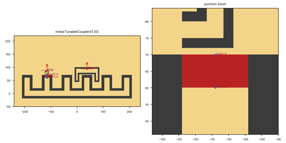
Pin image (default parameters). Light = metal, dark = etched gap, colours = junction layers. A red dot and arrow is a pin and its direction (out of the cell); the red bar is the CPW width a + 2 b. Blue dot = a pin without direction. Units: µm.
pin |
x (µm) |
y (µm) |
direction (°) |
a (µm) |
b (µm) |
purpose |
|---|---|---|---|---|---|---|
|
38 |
94 |
90 |
20 |
12 |
LOM node |
|
-114 |
87.5 |
90 |
20 |
12 |
control line (flux) in the LOM |
|
-114 |
60 |
none |
10 |
6 |
junction pins (the LOM’s L_J); LOM node |
|
-114 |
70 |
none |
10 |
6 |
junction pins (the LOM’s L_J); grounded in the LOM |
Pins with direction none: squid_a, squid_b. They mark a point (a junction lead, a pad centre), not a CPW end. The KLayout ghost draws them as boxes. A route can start there only where the notes say so; it cannot be snapped to.
a, b: CPW centre width and gap where the pin declares them (– = not declared). Position and direction are in the cell’s own frame (at=(0, 0), rot=0).
Parameters
name |
default |
unit |
description |
|---|---|---|---|
|
|
μm |
Width of center conductor |
|
|
μm |
Width of gap |
|
|
μm |
Turn radius |
|
|
– |
Junction as fabricated: Metal footprint, or a trilayer cell placed on each junction line |
|
|
– |
Trilayer junction cell parameters (JSON dict, e.g. lj_nH) |
|
|
– |
Quantum Metal component |
|
|
– |
Metal options as JSON (bare numbers on length options are µm) |
|
|
– |
Pins left open (comma-separated): keep Metal’s etch beyond them, as drawn with no route attached |
Electrically relevant parameters (sizes, gaps, junction, ports) come first, the rest follows.
LOM model
The cell contributes to the lumped model:
branch |
type |
nodes |
value (estimate at defaults) |
|---|---|---|---|
|
C |
island – gnd |
estimate=21, unit=fF, estimate_source=rough: 6-finger comb to ground (Igreja & Dias), estimate_kind=rough, uncertainty=±50% |
|
SQUID |
island – gnd |
Lj_nH=10, Cj_fF=0, asym=0, flux_phi0=0 |
|
C |
island – Control |
estimate=6, unit=fF, estimate_source=rough: coupler arm (CPS), estimate_kind=rough, uncertainty=±50% |
|
C |
Control – gnd |
estimate=7.6, unit=fF, estimate_source=rough: arm, estimate_kind=rough, uncertainty=±50% |
Nodes: island, Control.
How to use
In Python:
from quantcore_circuits.designer import Designer

d = Designer("demo", box=(0, 0, 7500, 7500))
d.add("U1", "metal:TunableCoupler01", at=(3750, 3750), a=10)   # parameters: see the table above
d.add("PAD", "BondPad", at=(1125, 3750), rot=270)   # a launcher to connect to
d.route("L1", "PAD.a", "U1.Control")                # a CPW from the pad to the pin
Pin names go into d.route(...) as INSTANCE.pin, and into snap= / to= when placing. From the shell: qcc components metal:TunableCoupler01 lists the pins; add --schema for the parameters.
In KLayout: Quantcore panel ▸ Components ▸ double-click the cell, then click on the layout to place it. Rotate and mirror before the click; use Connect on two pins to route.