3X SQUID cell (chip_10a)
Not a full chip but one SQUID cell: two small Nb trilayer junctions side by side in one loop (0.2 µm fingers, windows 16 µm apart). A SQUID like this makes a qubit tunable by flux. The legacy script was unfinished and drew only a pair of fingers; the rebuild completes the cell the way the script’s commented-out lines intended.
It comes from Quantcore’s QWri script chip_10a_3X_SQUID.py (internal, used for the chip_05 SQUIDs). The rebuild places the cell in the middle of an otherwise empty PDK die with the device ID CHIP10A 3X. Build it to see a junction-sized structure (tens of µm) inside a 7.5 mm die. The whole-chip picture is nearly empty, so use the close-up.
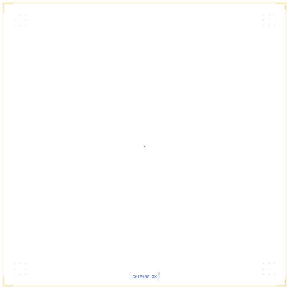
At a glance
Notebook |
|
Source |
Quantcore legacy QWri script |
Chip |
7.5 × 7.5 mm Quantcore die, sapphire |
On the chip |
1 |
Builds today |
yes, rebuilt from its JSON on 2026-11-19 in 0.9 s (the notebook itself was not re-run) |
Pictures
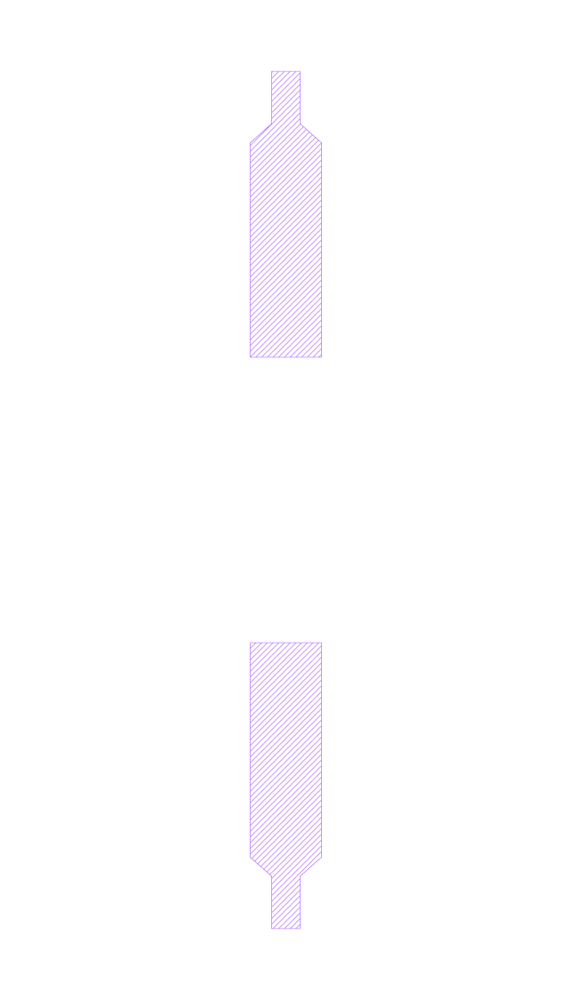
What the legacy script actually drew: only the two straight fingers (render of the legacy GDS).
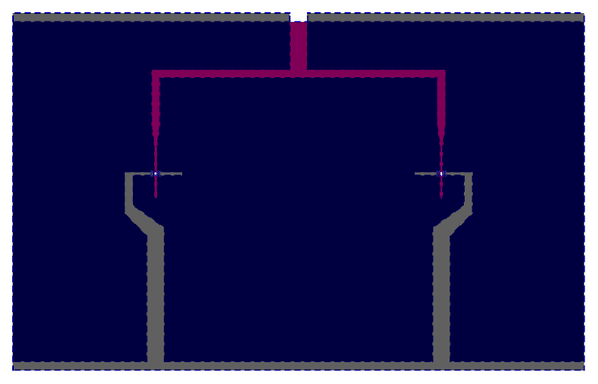
The rebuilt SQUID cell, about 56 µm wide: two junction sites 16 µm apart, both fed from one lead above.
LOM estimates
The notebook has no saved LOM output. The chip has no qubit or resonator, so its LOM netlist is empty.
Build spec
The rest of this page is the detailed spec the notebook was built from: every component, the changes made while rebuilding, and the notes.
Source: components/python/chip_10a_3X_SQUID.py (create_squid(js=1.0, secondFinger=0, path=...), writes
squid_3x_SQ_<js>.gds; __main__ calls create_squid(2)). Legacy QWri library, Quantcore internal (header:
“THIS FILE IS USED FOR CHIP_05 SQUIDS”). Notebook examples/designs/legacy/chip_10a_3x_squid.ipynb.
Changes made in the rebuild
Completed:
SQ=TrilayerSquidHSQ(0.1·js = 0.2 µm straight × 0.2 µm bent at x = ±8 µm, 32 × 20 µm windows, HSQ + gradient) at the die centre, as in the script’s commented-out insertions; the drawn positivetop_fingerpair moved 100 µm up (it would sit in the left window). PDK junction rule (Nb trilayer, Δ = 1.4 meV, I_c·R_n = πΔ/2e = 2.20 mV, R_n 40–50 kΩ, qubits 4–8 GHz; PDK processget_pdk().junction: R_n·A 13.5 kΩ·µm², C_J 50 fF/µm², both assumed by the PDK): 337.5 kΩ per junction, 168.75 kΩ parallel (L_J 25 nH).The notebook’s JSON was rebuilt from its layout cell. The notebook has not been re-run, so its outputs are cleared and its PNGs may be out of date.
What it is: a work-in-progress SQUID junction generator, not a chip. Of everything it sets up (three
JJ_finger Top / JJ_finger Bottom pairs, negative 32 × 20 µm windows at x = ±8 µm, HSQ boxes, the merge into
JUNC_<js>), only one thing is drawn: cell top_finger holds two positive straight fingers (JJ_finger Top,
negative=False, window 0.5 × 0.5 µm, finger length 0.8 µm, x = 8, y = 0, finger width 0.4 µm, pad width 1.0 µm;
conn_height=0.4 is not a parameter of that PCell). Every insertion into bottom_finger and JUNC_<js>, the HSQ
boxes and the final merge are commented out, so JUNC_2 and bottom_finger are written empty. The output is three
top cells; only top_finger has geometry (2/0, 6.96 µm²).
Builds: yes. JJFingerStraight (components; golden test_jj_finger_straight[top3] covers this
parameter set).
Components (legacy frame, cell top_finger)
instance |
legacy cell → catalog ref |
params |
at |
notes |
|---|---|---|---|---|
FA |
|
|
|
the PCell’s own |
FB |
same |
same |
|
Never drawn (computed, then commented out): bottom (negative) fingers 0.1·js = 0.2 µm wide (finger_length 3.2,
window 32 × 20, x = ±8, y = −3.6), bent fingers secondFinger or 0.1·js = 0.2 µm (finger_length 3, window 32 × 19,
y = −2), HSQ boxes 0.2 µm wide with a 30 nm overlap: the intended SQUID is two 0.2 × 0.2 µm junctions at x = ±8 µm.
No die in the source (it writes the bare cells). Rebuilt on the PDK v2 die frame, the cell at the die centre, with
the device ID CHIP10A 3X.
Routes, LOM
No routes, no pads, no ports: the LOM netlist is empty. “LOM simulation” = a junction table of the intended (undrawn) junctions: 0.2 × 0.2 µm² single and as a two-junction SQUID, with an assumed Jc. No sim groups.
Keep-outs
None.