MunchQubits (KQC)
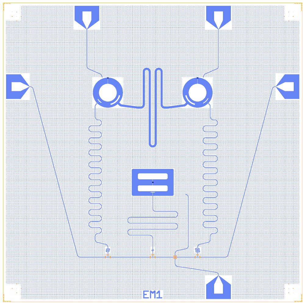
A KQCircuits chip with two circular transmons joined by a long resonant coupler, and a third, floating double-pad qubit. All three are read out through one probe line. It is rebuilt on the Quantcore PDK.
Build it to see the circular and double-pad qubit components, a resonant coupler between two qubits, and a charge line that crosses a probe line on an airbridge.
At a glance
Notebook |
|
Source |
KQCircuits |
Chip |
10 × 10 mm, SMA8 launchers, chip name “EM1” |
On the chip |
2 circular transmons · 1 floating double-pad qubit · 9.8 mm resonant coupler · 3 λ/2 readouts (11500, 12700, 8000 µm) · 1 probe line · 3 charge lines |
Builds today |
yes (layout built on 2026-11-19 in 10 s) |
How the notebook builds it
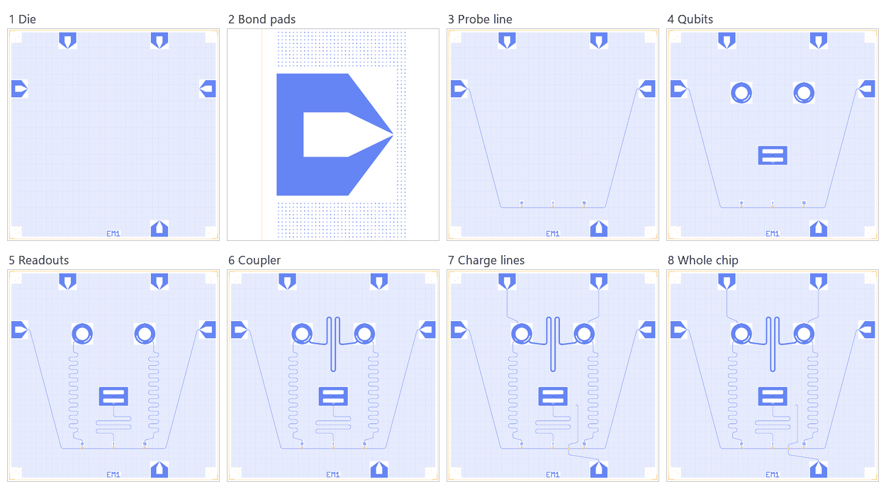
Die. The empty 10 × 10 mm chip with the Quantcore frame (dicing marks, alignment grids, chip boundary, device ID) and the SMA8 launchers.
Bond pads. The launchers moved so their outer etch edge sits 100 µm from the die edge (the pad rule).
Probe line. Splitters on the probe line and the readout capacitors.
Qubits. Two circular transmons and the double-pad qubit with Quantcore SQUIDs.
Readouts. Three λ/2 resonators.
Coupler. The 9.8 mm resonant coupler between the two circular qubits.
Charge lines. One per qubit; QB3’s crosses the probe line on an airbridge.
Whole chip. Sim groups, centring, design saved.
LOM estimates
Numbers are from a run of this notebook on 2026-11-19 (Setup, Design, Check and the LOM cells, 13 s): QuCat normal modes with QuTiP dressed values.
group |
qubit |
f_q (GHz) |
α (MHz) |
resonator |
f_r (GHz) |
κ (MHz) |
χ (MHz) |
|---|---|---|---|---|---|---|---|
QB1+QB2+CPL |
QB1 |
4.016 |
-64.5 |
CPL |
5.526 |
0 |
-8.14 |
QB1+RR1 |
QB1 |
4.212 |
-95.9 |
RR1 |
5.237 |
5.46 |
-1.01 |
QB2+RR2 |
QB2 |
4.229 |
-88.4 |
RR2 |
4.7 |
9.08 |
-5.71 |
QB3+RR3 |
QB3 |
5.322 |
-166 |
RR3 |
7.657 |
1.06 |
-0.488 |
group |
pair |
ZZ (kHz) |
neighbours |
hybridised |
|---|---|---|---|---|
QB1+QB2+CPL |
QB1-QB2 |
– |
yes |
yes |
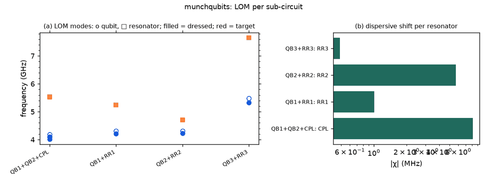
These are lumped-model estimates (component formulas and calibration), not FEM results; see the LOM page for how far to trust them.
Build spec
The rest of this page is the detailed spec the notebook was built from: every component, port, route and length.
Source other-libs/KQCircuits-main/KQCircuits-main/klayout_package/python/kqcircuits/chips/munch_qubits.py
(MunchQubits, chip name “EM1”), GPL-3.0 (IQM Finland). Rebuilt from extracted parameters. What it is: 2
grounded CircularTransmonSingleIsland qubits (QB1, QB2) linked by a 9.8 mm resonant coupler (a=3 b=32), and a
floating DoublePads qubit (QB3). Each qubit has a long meandered readout resonator, coupled through a
SmoothCapacitor to a T in one probeline along y = 1500. There are 3 drive lines; QB3’s drive crosses the probeline
on an airbridge. There are no flux lines and no junction tests. 10 × 10 mm, KQC frame = Designer frame, face 1t1.
Checked on 2026-11-02: lengths match KQC, including the probeline (16653.1 µm + 3 × 250 µm
inside the T’s = KQC 17403.1).
Components
instance |
catalog ref |
key params (units) |
at (x, y) |
rot |
notes |
|---|---|---|---|---|---|
QB1 |
|
|
(3500, 7000) |
0 |
coupler_1 SW (3146.45,6646.45) = readout; coupler_2 SE (3853.55,6646.45) = coupler; drive (3311.89,7516.83) |
QB2 |
|
|
(6500, 7000) |
0 |
coupler_1 SE (6853.55,6646.45) readout; coupler_2 SW (6146.45,6646.45) coupler; drive (6688.11,7516.83) |
QB3 |
|
|
(5000, 4000) |
180 |
cplr (5000,3550) facing down; drive (6100,3600) |
T1, T3, T2 |
|
|
(3500,1500), (5000,1500), (6500,1500) |
0 |
probeline tees (KQC: inline nodes |
CK1, CK2, CK3 |
|
|
snap |
(→ 90) |
κ caps; b at (x, 1810) facing up |
CIRC = dict(r_island=300, ground_gap=200, squid_angle=90, drive_distance=550, couplers_r=400, couplers_a=[10,3], couplers_b=[6,32], couplers_width=[30,50]).
Routes
route |
from → to |
type, length (µm) |
waypoints |
notes |
|---|---|---|---|---|
CPL |
QB1.coupler_2 → QB2.coupler_2 |
meander=9800, a=3 b=32 |
(4500,6500), (5500,6500) |
resonant coupler (λ/2 bus); meander auto on (4500→5500) |
PL_in |
chip.PL-1-IN → T1.a |
cpw 6926.55 |
(2500, 1500) |
diagonal from (900,7200) to (2500,1500) |
PL_13 / PL_32 |
T1.c → T3.a / T3.c → T2.a |
1400 / 1400 |
none |
|
PL_out |
T2.c → chip.PL-1-OUT |
6926.55 |
(7500, 1500) |
diagonal up to (9100,7200) |
RR1 |
QB1.coupler_1 → CK1.b |
meander=11500 |
(3075.736,6275.736), (3075.736,2110), (3075.736,2010), (3500,1910) |
meander auto on the long vertical |
RR2 |
QB2.coupler_1 → CK2.b |
meander=12700 |
(6924.264,6275.736), (6924.264,2110), (6924.264,2010), (6500,1910) |
|
RR3 |
QB3.cplr → CK3.b |
meander=8000 |
(5000,3150), (5000,2110) |
straight down |
DL1 |
chip.DL-QB1 → QB1.drive |
cpw |
(2800, 7900) |
|
DL2 |
chip.DL-QB2 → QB2.drive |
|
(7200, 7900) |
|
DL3 |
chip.DL-QB3 → QB3.drive |
|
(5750,1200), wp((5750,1500), airbridge=True), (5750,1700), (6193.979,1800) |
crosses PL_32 on an AirbridgeConnection |
d = Designer("kqc_munch", chip={"name_chip": "EM1"},
             launchers={"type": "SMA8", "assign": {1: "DL-QB1", 2: "DL-QB2", 3: "PL-1-OUT", 5: "DL-QB3", 8: "PL-1-IN"}})
m1 = d.add("QB1", "CircularTransmonSingleIsland", at=(3500, 7000), junction=J, drive_angle=110,
           couplers_angle=[225, 315], couplers_arc_amplitude=[25, 65], **CIRC)            # QB2 likewise
DP = dict(coupler_extent=[150, 20], island1_extent=[1000, 200], island2_extent=[1000, 200], island_island_gap=200,
          ground_gap=[1400, 900], drive_position=[-1100, 400])
m3 = d.add("QB3", "DoublePads", at=(5000, 4000), rot=180, junction=J, **DP)
d.route("CPL", m1.coupler_2, "QB2.coupler_2", meander=9800, a=3, b=32, nodes=[(4500, 6500), (5500, 6500)])
for k, x in {1: 3500, 3: 5000, 2: 6500}.items():
    d.add(f"T{k}", "WaveguideCoplanarSplitter", at=(x, 1500), angles=[180, 90, 0], lengths=[50, 150, 50], use_airbridges=True)
    d.add(f"CK{k}", "SmoothCapacitor", snap="a", to=f"T{k}.b", finger_control={1: 3.32, 2: 4.21, 3: 1.46}[k],
          finger_width=10, ground_gap=10, finger_gap=5, fixed_length=160)
d.route("RR3", m3.cplr, "CK3.b", meander=8000, nodes=[(5000, 3150), (5000, 2110)])        # RR1/RR2, PL_*, DL* as tabled
Launchers, pads, test structures, markers, labels
SMA8 with KQC names, 5 pads drawn: DL-QB1 #1 (2800,9200), DL-QB2 #2 (7200,9200), PL-1-OUT #3 (9200,7200), DL-QB3 #5 (7200,800), PL-1-IN #8 (800,7200). No junction tests. KQC inserts DL3 twice because of a loop-indentation bug in the source; build it once.
LOM node structure (qubit ↔ resonator ↔ feedline ↔ bus ↔ control lines)
QB1, QB2: a grounded island with C and JJ/SQUID to ground (
squid_angle=90), plus coupler nodes coupler_1 (readout) and coupler_2 (bus). QB3: two floating islands with the JJ between them and cplr from island 2. The KQC LOM models exist (lom/kqc_models.py), but their values are estimates.CPL: λ/2 TLres (port↔port meander), length 9800, a=3 b=32 (high Z). It couples QB1 and QB2 resonantly.
RRk: λ/2 TLres (11.5 / 12.7 / 8.0 mm, meander port↔port). CKk is the series C to the probeline node (T1, T3, T2 merged), and chip.PL-1-IN/OUT are 50 Ω ports. Expect low lumped f, a few GHz.
DLk:
drivecontrols. There are no flux controls (fixed-frequency in this layout).
Targets (if stated)
None. readout_res_lengths=[11500,12700,8000], kappa_finger_control=[3.32,4.21,1.46], coupler_length=9800.
Simplifications for a first rebuild
Build QB1 + QB2 + CPL + RR1/RR2 + the probeline first; QB3 and DL3 (the airbridge crossing) come second. The KQC
meanders carry n_bridges=18 (resonators) and 6 (coupler); airbridges are optional.
Quantcore PDK rebuild
The notebook is a Quantcore-PDK rebuild of the source chip. The netlist, LOM and imported components are kept, and the process is Quantcore’s.
Notebook: examples/designs/kqc/munchqubits.ipynb.
Chip: the Quantcore die frame (L dicing markers 1000/0, 3 × 3 alignment grids 1001/0, chip boundary 100/0, device ID where an edge is free; any brand text is QCT), drawn on the source’s 10 × 10 mm chip (its launchers sit on the chip edges, so the design does not fit the 7.5 mm die). KQC’s ChipFrame (dicing edge, corner markers, labels) is not drawn. KQC’s original grids its whole ground plane (
with_grid, 5 µm squares on a 10 µm step). The rebuild keeps that coverage at the PDK density instead (chip parametercheese: "chip",with_grid: false): 5 µm squares with 20 µm gaps over the whole die, at least 4 µm from the 3/0 keep-outs, inside the design area and clear of the frame markers and the device ID.Stack: sapphire 650 µm, εr 10.25 (the PDK default stack, used by the LOM estimates and every FEM export); KQC’s own simulation default is silicon (εr 11.45), so LOM capacitances and resonator frequencies here are for sapphire.
Junctions: Quantcore Nb/AlOx/Nb trilayer junctions (
junction_typefromlayouts.registry.trilayer_junction): fingers on 2/0 + 4/0, spacer 50/0 with the 51–53/0 gradient, sized on the PDK junction rule (Nb Δ = 1.4 meV, I_c·R_n = πΔ/2e, R_n·A 13.5 kΩ·µm² and C_J 50 fF/µm² assumed); every qubit’s SQUID becomes a Quantcore SQUID (KQC’sjunction_widthsets the straight finger). The two large circular islands (C_Σ ≈ 212 / 222 fF) are sized for 4.05 GHz, the bottom of the PDK band: 0.26 / 0.27 µm fingers, R_n 43.3 / 41.7 kΩ, L_J 6.48 / 6.24 nH; the double-pad qubit gets a PDK SQUID of two 0.25 × 0.6 µm junctions → R_n = 45 kΩ in parallel, L_J = 6.73 nH at zero flux, C_J = 15 fF (in the 40–50 kΩ window). This replaces the assumed 6 / 10 nH + 2 fF. Expected f_q ≈ 4.06 / 4.05 / 5.3 GHz (estimates; were 4.35 / 4.25 / 4.57 GHz).Kept: the topology and every KQC element with the source’s parameters, positions and orientations, the launcher assignment, every route’s path and length, the sim groups (the 9800 µm resonant coupler, readouts 11500 / 12700 / 8000 µm).