Google coupler plaquette
The smallest closed plaquette of Sycamore’s coupler lattice: four flux-tunable Xmon-type qubits on the corners of a square and a flux-tunable transmon coupler on each of the four bonds. Every qubit has a λ/4 readout, an XY line and a Z line; every coupler has a Z line. No Sycamore layout is public; the papers (Arute et al. 2019; Yan et al. 2018) give the targets, and the layout is ours (GPL).
This notebook tiles the lattice cell into a plaquette: the same qubit and coupler as google_tc_cell, mirrored round the die centre, with two feedlines and sixteen pads.
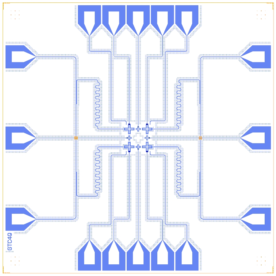
At a glance
Notebook |
|
Source |
Arute et al., Nature 574, 505 (2019); Yan et al., PR Applied 10, 054062 (2018); no public layout |
Chip |
10 × 10 mm Quantcore die, sapphire 650 µm (εr 10.25), CPW 10 / 6 µm |
On the chip |
4 qubits · 4 couplers · 4 λ/4 hangers · 2 feedlines · 16 bond pads |
Builds today |
yes (layout built on 2026-11-19 in 12 s) |
How the notebook builds it
Each Design segment is one cell with a picture of the chip so far (see the notebook template).
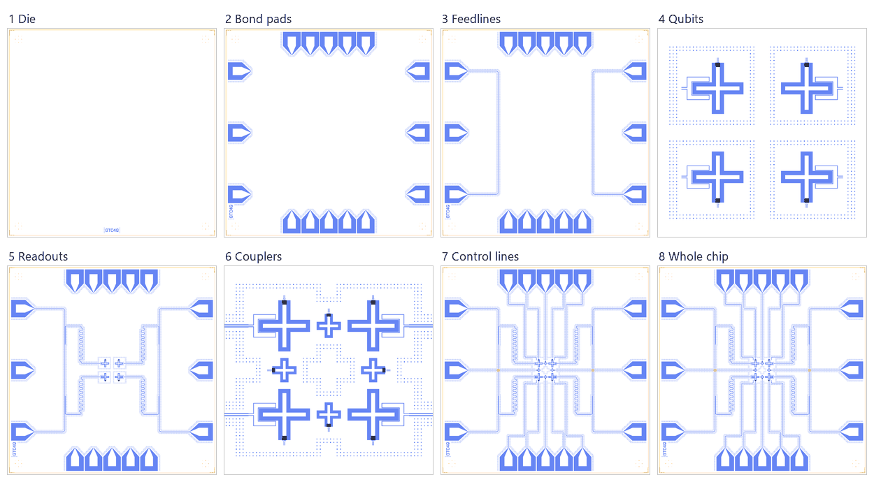
Die. A 10 × 10 mm die, because the plaquette needs sixteen pads.
Bond pads. Sixteen pads: feedline ends, an XY and a Z pad per qubit, a Z pad per coupler.
Feedlines. Two vertical feedlines, left and right.
Qubits. Four crosses with Quantcore trilayer SQUIDs.
Readouts. Four λ/4 readouts, each ending in a hanger on its feedline.
Coupling. Four coupler crosses and the declared capacitances.
Control lines. The XY and Z lines, with a KQC airbridge where a coupler’s Z line crosses a feedline.
Whole chip. The centring check, targets, sim groups and the save.
LOM estimates
Numbers are from a run of this notebook on 2026-11-19 (Setup, Design, Check and the LOM cells, 36 s): QuCat normal modes with QuTiP dressed values.
group |
qubit |
f_q (GHz) |
α (MHz) |
resonator |
f_r (GHz) |
κ (MHz) |
χ (MHz) |
|---|---|---|---|---|---|---|---|
Q00+R |
Q00 |
6.668 |
-236 |
R_Q00 |
4.487 |
0.663 |
-0.172 |
Q10+R |
Q10 |
6.668 |
-236 |
R_Q10 |
4.566 |
0.697 |
-0.196 |
Q01+R |
Q01 |
6.668 |
-236 |
R_Q01 |
4.527 |
0.68 |
-0.184 |
Q11+R |
Q11 |
6.668 |
-236 |
R_Q11 |
4.606 |
0.714 |
-0.21 |
L_J,c (nH) |
Φ/Φ0 |
f_c (GHz) |
α_c (MHz) |
f_q1 (GHz) |
f_q2 (GHz) |
2·abs(g̃) (MHz) |
g̃ (MHz) |
g̃ Yan Eq. 5 (MHz) |
ZZ (kHz), q2 detuned |
|---|---|---|---|---|---|---|---|---|---|
6 |
0 |
8.765 |
-424 |
6.567 |
6.577 |
10 |
5.01 |
5.1 |
-200 |
6.5 |
0.126 |
8.408 |
-423 |
6.567 |
6.575 |
7.7 |
3.85 |
3.98 |
-155 |
7 |
0.172 |
8.09 |
-421 |
6.567 |
6.572 |
4.7 |
2.35 |
2.53 |
-114 |
7.25 |
0.19 |
7.944 |
-418 |
6.567 |
6.57 |
2.84 |
1.42 |
1.64 |
-97.9 |
7.5 |
0.205 |
7.806 |
-414 |
6.567 |
6.568 |
0.664 |
0.332 |
0.614 |
-89.1 |
7.75 |
0.218 |
7.675 |
-408 |
6.567 |
6.565 |
1.91 |
-0.955 |
-0.596 |
-92 |
8 |
0.23 |
7.551 |
-400 |
6.562 |
6.567 |
5 |
-2.5 |
-2.03 |
-115 |
8.5 |
0.251 |
7.322 |
-367 |
6.554 |
6.567 |
13.5 |
-6.73 |
-5.87 |
-296 |
9 |
0.268 |
7.118 |
-302 |
6.54 |
6.567 |
27.2 |
-13.6 |
-11.7 |
-1030 |
9.25 |
0.275 |
7.027 |
-256 |
6.53 |
6.567 |
37.5 |
-18.8 |
-15.8 |
-2060 |
9.5 |
0.282 |
6.943 |
-207 |
6.515 |
6.567 |
51.7 |
-25.9 |
-20.9 |
-4400 |
group |
qubit |
f_q (GHz) |
α (MHz) |
resonator |
f_r (GHz) |
κ (MHz) |
χ (MHz) |
|---|---|---|---|---|---|---|---|
Q00–CB–Q10 |
Q10 |
6.119 |
-229 |
– |
– |
– |
– |
Q01–CT–Q11 |
Q01 |
6.119 |
-229 |
– |
– |
– |
– |
Q00–CL–Q01 |
Q01 |
6.119 |
-229 |
– |
– |
– |
– |
Q10–CR–Q11 |
Q10 |
6.119 |
-229 |
– |
– |
– |
– |
group |
pair |
ZZ (kHz) |
neighbours |
hybridised |
|---|---|---|---|---|
Q00–CB–Q10 |
Q00-Q10 |
-88.5 |
yes |
no |
Q00–CB–Q10 |
CB-Q10 |
-7610 |
yes |
no |
Q00–CB–Q10 |
CB-Q00 |
-17000 |
yes |
no |
Q01–CT–Q11 |
Q01-Q11 |
-88.5 |
yes |
no |
Q01–CT–Q11 |
CT-Q01 |
-7610 |
yes |
no |
Q01–CT–Q11 |
CT-Q11 |
-17000 |
yes |
no |
Q00–CL–Q01 |
Q00-Q01 |
-88.5 |
yes |
no |
Q00–CL–Q01 |
CL-Q01 |
-7610 |
yes |
no |
Q00–CL–Q01 |
CL-Q00 |
-17000 |
yes |
no |
Q10–CR–Q11 |
Q10-Q11 |
-88.5 |
yes |
no |
Q10–CR–Q11 |
CR-Q10 |
-7610 |
yes |
no |
Q10–CR–Q11 |
CR-Q11 |
-17000 |
yes |
no |
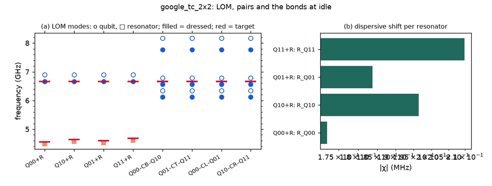
These are lumped-model estimates (component formulas and calibration), not FEM results. The LOM page says how far to trust them.
Build spec
The rest of this page is the detailed spec the notebook was built from, with every component, port, route and length.
Sources. As google_tc_cell.md: Arute et al., Nature 574, 505 (2019) and SI (arXiv:1910.11333): square
lattice of transmons with a tunable coupler on every nearest-neighbour bond (54 qubits, 88 couplers), per-qubit XY
and Z lines, a Z line per coupler, Table 2 parameters, g̃ from +5 to −40 MHz; Yan et al., PR Applied 10, 054062
(2018): scheme, Eq. (5).
Licence. Papers cited for parameters only (no public layout); layout and code ours, GPL.
What it is. The smallest closed plaquette of the coupler lattice: 4 flux-tunable Xmon-type qubits at the corners
of a square (qubit pitch 660 µm), 4 flux-tunable couplers on the bonds; same qubit, coupler, junctions and
coupling gaps as google_tc_cell.
Chip. 10 × 10 mm, Quantcore die frame (QCT), device ID GTC4Q; sapphire 650 µm, εr 10.25; 10/6 µm CPW;
Quantcore trilayer SQUIDs (L_J 6.01 nH, R_n ≈ 40 kΩ, C_J 16.8 fF) on all eight crosses. 16 BondPads (5 bottom,
5 top, 3 per side).
Notebook. examples/designs/google/google_tc_2x2.ipynb.
Components
instance |
catalog ref |
key params (µm) |
at (x, y) |
rot |
notes |
|---|---|---|---|---|---|
Q00, Q10, Q01, Q11 |
metal:TransmonCrossFL |
cross 160 / 30 / 30, claw |
(5000 ∓ 330, 5000 ∓ 330) |
0 (bottom), 180 (top) |
SQUID arm points out of the plaquette in y |
CB, CT, CL, CR |
metal:TransmonCrossFL |
cross 70 / 20 / 20, no claws, flux line |
bond midpoints |
0, 180, −90, 90 |
SQUID arm points out of the plaquette |
XY_*_end |
metal:OpenToGround |
outer diagonal of each cross (−110, −170 from its centre, mirrored) |
±90 |
XY drive ends |
|
pads |
BondPad |
edges |
FLL/FLR in/out, Z_CL/Z_CR (sides), XY/Z per qubit + Z_CB/Z_CT (bottom/top) |
Routes
route |
from → to |
type, length |
notes |
|---|---|---|---|
FLL, FLR |
side pads |
cpw, 9014 µm |
vertical feedlines at x = 2700 / 7300 |
R_Q00 … R_Q11 |
claw → hanger |
meander 6243 / 6122 / 6182 / 6064 µm |
λ/4, hanger 900 µm at y = 3300 / 6700, ground gap 4, short |
XY_*_line |
pad → XY end |
cpw 4624 µm |
|
Z_Q*_line, Z_CB/CT_line |
flux line → pad |
cpw |
|
Z_CL_line, Z_CR_line |
flux line → side pad |
cpw, airbridge over FLL / FLR |
the only crossings |
LOM node structure
8 grounded islands with SQUIDs; on each bond C_QC (2.35 fF) qubit–coupler twice and C_QQ (0.28 fF) qubit–qubit; the
two diagonals 0.08 fF (all d.couple CPS estimates; the Q3D job plaquette replaces them); readout claws → λ/4
TLres → HANGER → FLL / FLR; XY ends 50 Ω; Z lines flux_bias controls.
Targets and LOM values
quantity |
source |
rebuild (LOM) |
|---|---|---|
f_q |
6.661 GHz idle |
6.668 GHz (qubit + readout); 6.567 GHz with the coupler at the off point; checkerboard partner 6.119 GHz |
α |
−208 MHz |
−237 MHz alone, −225 MHz with the coupler |
f_r |
4.618 GHz median |
4.56 / 4.60 / 4.64 / 4.68 GHz targets (lengths set for them) |
κ |
0.64 MHz |
≈ 0.67–0.72 MHz |
g̃ |
+5 … −40 MHz |
+5.0 MHz (f_c 8.77 GHz) → 0 at 7.77 GHz → −18.8 MHz (7.03 GHz) → −25.9 MHz (6.94 GHz) |
static ZZ at idle |
– |
−88 kHz per bond (couplers off, checkerboard 0.45 GHz) |
Simplifications / adaptations
Planar die: two feedlines (no Purcell filters), two airbridges; axis-aligned plaquette (Sycamore’s is diagonal); the plaquette idle is simulated bond by bond (eight junctions in one QuCat network exceed its symbolic solver).