Vortex neck test chip (QPDK)
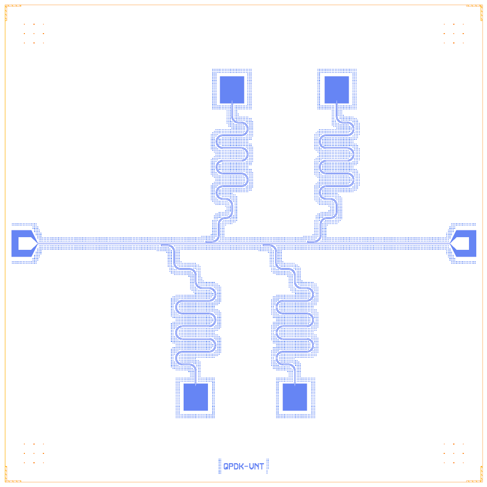
One feedline with four λ/4 hanger resonators. Each resonator is shorted to ground through a narrow neck, a 2 µm × 325 µm constriction inside a window of vortex-trap holes. The layout comes from QPDK’s vortex_neck_test_chip.pic.yml (MIT) and is rebuilt on the Quantcore PDK; the rebuild is GPL-3.0.
This notebook is an example of a device under test that is not a qubit (the neck termination) and of hangers placed on alternate sides of a line.
At a glance
Notebook |
|
Source |
gdsfactory |
Chip |
7.5 × 7.5 mm Quantcore die, the source’s 4.8 × 5.6 mm circuit centred in it, CPW 10 / 6 µm |
On the chip |
2 launchers · 1 feedline · 4 neck terminations · 4 λ/4 resonators |
Builds today |
yes (layout built on 2026-11-19 in 5 s) |
How the notebook builds it
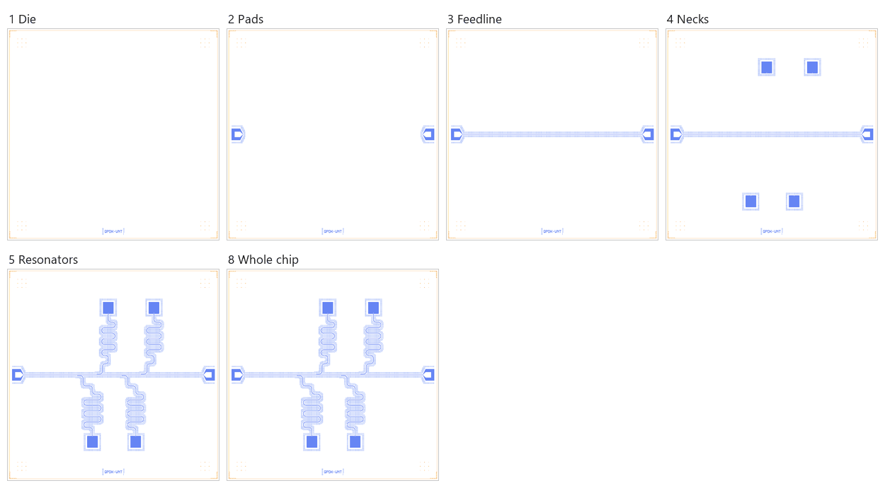
Die. The Quantcore die with the frame and the device ID.
Bond pads. Two launchers at the die edges.
Feedline. A straight line from launcher to launcher.
Necks. Four neck terminations at the source’s positions (the chip has no qubits).
Resonators. Four λ/4 resonators from the necks to hanger sections on the feedline.
Coupling. Only the hangers.
Control lines. None.
Whole chip. One sim group, centring, save.
LOM estimates
Numbers are from a run of this notebook on 2026-11-19 (Setup, Design, Check and the LOM cells, 6 s): QuCat normal modes with QuTiP dressed values.
mode |
kind |
f (GHz) |
κ (MHz) |
A (MHz) |
participation |
|---|---|---|---|---|---|
R_p600 |
resonator |
4.522 |
0.0172 |
0 |
R_p600 1.00 |
R_p300 |
resonator |
4.726 |
0.0196 |
0 |
R_p300 1.00 |
R_0 |
resonator |
4.949 |
0.0225 |
0 |
R_0 1.00 |
R_m300 |
resonator |
5.193 |
0.026 |
0 |
R_m300 1.00 |
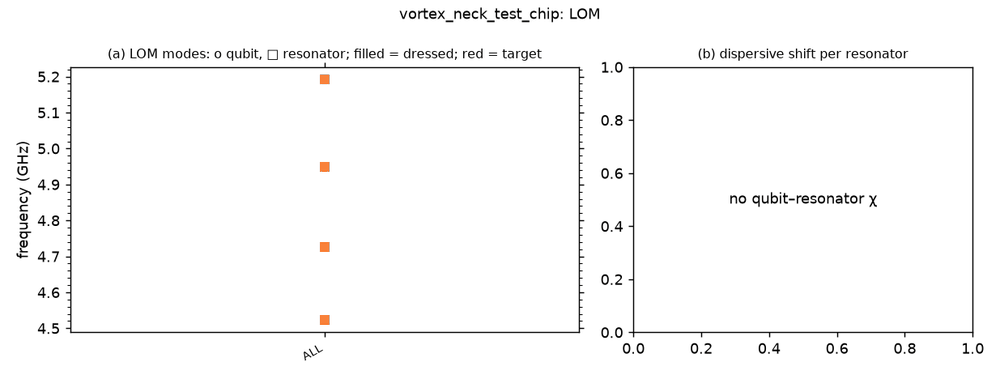
These are lumped-model estimates (component formulas and calibration), not FEM results. The LOM page says how far to trust them.
Build spec
The rest of this page is the detailed spec the notebook was built from, with every component, port, route and length.
Source: qpdk/samples/vortex_neck_test_chip.pic.yml
· cells qpdk/cells/vortex.py (neck_termination) and qpdk/cells/resonator.py (resonator_coupled) · licence MIT
(verified) · Read on 2026-11-02. No image in the repo.
What it is: one straight feedline with 4 hanger resonators alternating below and above it. Each resonator is open at
the coupled end. Its far end runs through a CPW lead into a neck_termination: a 100 µm linear taper into a 2 µm-wide,
325 µm-long neck that shorts to ground inside a 380 µm window lined with vortex-trap holes. Names give the length
offset from 4000 µm: p600 = 4600, m300 = 3700, p300 = 4300, 0 = 4000.
Frame: no chip edge in the YAML. Extent is x 0…4600, y about ±2650 (necks at ±2200 plus ≈450 µm of taper and neck).
Use box (0, 0, 4800, 5600), Designer = source + (100, 2800). Si, M1 negative.
The chip is built with NeckTermination.
Components
instance |
catalog ref |
key params (units) |
at (x, y) Designer |
rot |
notes |
|---|---|---|---|---|---|
PW |
|
default |
(100, 2800) |
270 (faces east) |
launcher_west (0, 0) |
PE |
|
default |
(4700, 2800) |
90 (faces west) |
launcher_east (4600, 0) rot 180 |
N_p600 |
|
taper_length 100 (linear), neck_width 2, neck_length 325, window_width 380, trap_hole_rows 4, trap_hole_size 4, trap_hole_pitch 5.5, trap_hole_offset 6, trap_hole_keepout 24 |
(1643.9, 600) |
270 (points −y) |
source (1543.919, −2200) rot −90 |
N_m300 |
same |
same |
(2215.3, 5000) |
90 (points +y) |
source (2115.347, 2200) |
N_p300 |
same |
same |
(3201.1, 600) |
270 |
source (3101.061, −2200) |
N_0 |
same |
same |
(3858.2, 5000) |
90 |
source (3758.204, 2200) |
Routes
resonator_coupled: coupling_straight_length 200 µm, coupling_gap 20 µm edge-to-edge, so centre spacing 30 µm and
ground_gap = 30 − 5 − 6 − 5 − 6 = 8 µm. Each resonator is placed with its coupled section 30 µm off the feedline
(source y ∓30), starting at source x = 1006 / 1706 / 2606 / 3306. Feedline FL runs PW.a (≈400) → PE.a (≈4400), so the
coupler centre is at s = x_source + 100 + 100 − 400. The open end is at the west end of the coupled section, so
use end="open", direction backward.
route |
from → to |
type, length |
hanger (s, length, side, ground_gap, direction, end) |
notes |
|---|---|---|---|---|
FL |
PW.a → PE.a |
cpw |
straight y 2800 |
feed_res_* + feed_out chain |
R_p600 |
N_p600.o1 → FL.hanger |
meander 4600 (+ lead) |
806, 200, right, 8, backward, open |
below FL |
R_m300 |
N_m300.o1 → FL.hanger |
meander 3700 (+ lead) |
1506, 200, left, 8, backward, open |
above FL (mirrored) |
R_p300 |
N_p300.o1 → FL.hanger |
meander 4300 (+ lead) |
2406, 200, right, 8, backward, open |
below |
R_0 |
N_0.o1 → FL.hanger |
meander 4000 (+ lead) |
3106, 200, left, 8, backward, open |
above |
The source counts the length in three parts: resonator cell length (meandered, 6 meanders), then a route_bundle_cpw
lead from resonator_o2 to the neck (≈ |y| 2200 minus the meander height), then the neck itself. For a first rebuild,
set meander = listed length + ~600 µm of lead. Exact lead lengths need the built QPDK geometry.
Launchers, pads, test structures, markers, labels
2 launchers. The vortex-trap holes are part of each neck window. No fill or chip edge in this sample.
LOM node structure
FL: one conductor, two 50 Ω ports. Each R_x is a λ/4 resonator, open (capacitive) at the coupled end, with κ to FL. Its shorted end goes through a lumped series inductance: the neck, 325/2 ≈ 160 squares of kinetic plus geometric inductance, with a linear taper. No qubits.
Targets
None stated. λ/4 on Si: 4000 µm ≈ 7.5 GHz. The neck inductance pulls each mode down; the ±300/600 µm length steps separate the four modes.
Simplifications for a first rebuild
Replace each neck with a shorted
Designer.free_end(at, dir, term=0)at the neck position. The geometry is then plain λ/4 hangers.The component neck_termination: a CPW taper (10/6 µm → 2 µm centre over 100 µm), then a 2 × 325 µm neck shorted to ground, inside a 380 µm-wide etched window with 4 rows of 4 µm trap holes (pitch 5.5 µm). Ports:
o1(CPW). LOM: series L_neck to ground.
Build
The notebook examples/designs/qpdk/vortex_neck_test_chip.ipynb uses NeckTermination (QPDK defaults; o1 at the
source neck placement, rot ∓90). The lead is computed from the QPDK cells instead of the +600 µm estimate: resonator(L, 6 meanders) with R 100 µm puts resonator_o2 1200 µm out and (L − 600π)/7 east; each neck is 150.06 µm further east
and 970 µm further out, so the lead is one 90° bend, 150.06 + 970 − 200 + 50π = 1077.1 µm; route = L + 1077.1 µm
(N.o1 → open end), the neck adds 425 µm. LOM (lom NeckTermination model: neck at its inductive-equivalent length,
425 µm → ≈ 1279 µm of 10/6 CPW, rough, geometric L only): λ/4 4.59 / 4.80 / 5.03 / 5.28 GHz (p600 / p300 / 0 / m300),
κ 0.014–0.022 MHz on sapphire. With plain CPW ends and the 600 µm lead estimate the modes were at 5.68–6.76 GHz. The meander shape
is the router’s (between neck and coupler), not QPDK’s.
Quantcore PDK rebuild
The notebook is a Quantcore PDK rebuild, not a replica: the netlist, LOM and imported components are kept, the process is Quantcore’s.
Notebook: examples/designs/qpdk/vortex_neck_test_chip.ipynb.
Chip: the Quantcore die frame (L dicing markers 1000/0, 3 × 3 alignment grids 1001/0, chip boundary 100/0, device ID where an edge is free; any brand text is QCT), on the 7.5 × 7.5 mm Quantcore die; the source’s 4.8 × 5.6 mm chip area is centred in it (
box=QP.die_box(W, H)), so every coordinate stays the source’s.Stack: sapphire 650 µm, εr 10.25 (the PDK default stack, used by the LOM estimates and every FEM export); QPDK’s process is Al on Si (εr 11.45), so frequencies are not the QPDK ones.
Junctions: none on this chip (resonators with Nb necks only).
Kept: the topology and every component with the source’s parameters and positions, the readout / resonator lengths and coupled sections, the sim groups (the four lengths 4000 µm + 600 / −300 / +300 / 0 µm, the
NeckTerminations).