Seven-qubit processor
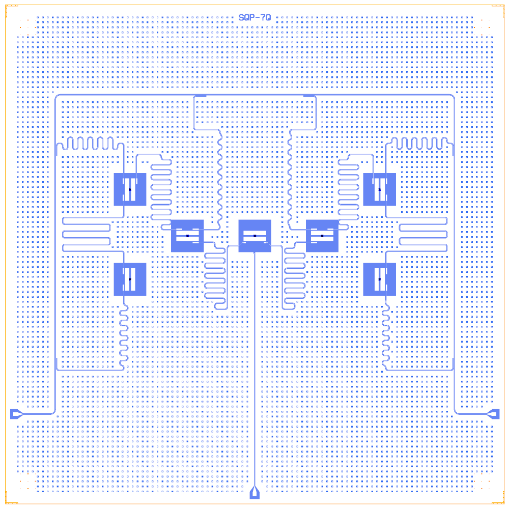
A community seven-qubit planar processor: a chain of pocket transmons joined by λ/2 buses, six λ/4 readouts hanging on a ∩-shaped feedline and one charge line. The source is a Qiskit Metal repository by A. Dahima (the README says MIT, but the repository has no LICENSE file); the notebook is a Quantcore PDK rebuild, distributed under GPL-3.0.
This notebook is an example of a coupled qubit chain with buses, a feedline that wraps around the qubits, and junctions sized per qubit from a frequency target.
At a glance
Notebook |
|
Source |
|
Chip |
10 × 10 mm Quantcore die (the source’s chip size) |
On the chip |
3 launchpads · 1 ∩ feedline · 7 pocket transmons · 6 λ/4 readouts · 6 λ/2 buses · 1 charge line |
Builds today |
yes (layout built on 2026-11-19 in 16 s) |
How the notebook builds it
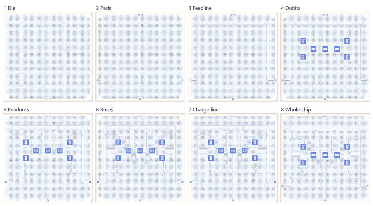
Die. The 10 × 10 mm die with the frame and the device ID
SQP-7Q.Bond pads. Three launchpads (feedline in and out, charge line).
Feedline. A ∩-shaped line round the chain.
Qubits. Seven pocket transmons, junctions sized for 4.80 to 5.20 GHz.
Readouts. Six λ/4 hanger readouts on the feedline.
Coupling. Six λ/2 buses between neighbouring qubits.
Charge line. Q4’s line, straight down to its pad.
Whole chip. Sim groups, targets, centring of the core, save.
LOM estimates
Numbers are from a run of this notebook on 2026-11-19 (Setup, Design, Check and the LOM cells, 56 s): QuCat normal modes with QuTiP dressed values.
group |
qubit |
f_q (GHz) |
α (MHz) |
resonator |
f_r (GHz) |
κ (MHz) |
χ (MHz) |
|---|---|---|---|---|---|---|---|
Q0R |
Q0 |
4.934 |
-390 |
R_Q0 |
6.777 |
0.125 |
-2.96 |
Q1R |
Q1 |
5.069 |
-347 |
R_Q1 |
6.87 |
0.13 |
-3.81 |
Q3R |
Q3 |
4.766 |
-359 |
R_Q3 |
6.961 |
0.135 |
-2.83 |
Q5R |
Q5 |
4.87 |
-355 |
R_Q5 |
7.053 |
0.14 |
-2.93 |
Q2R |
Q2 |
5.165 |
-344 |
R_Q2 |
7.147 |
0.146 |
-3.53 |
Q6R |
Q6 |
5.042 |
-386 |
R_Q6 |
7.238 |
0.152 |
-2.55 |
group |
pair |
ZZ (kHz) |
neighbours |
hybridised |
|---|---|---|---|---|
Q0_Q1 |
Q0-Q1 |
17.6 |
yes |
no |
Q3_Q4_Q5 |
Q3-Q5 |
-0 |
no |
no |
Q3_Q4_Q5 |
Q3-Q4 |
-2.25 |
yes |
no |
Q3_Q4_Q5 |
Q4-Q5 |
-4.14 |
yes |
no |
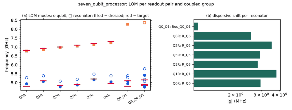
These are lumped-model estimates (component formulas and calibration), not FEM results. The LOM page says how far to trust them.
Build spec
The rest of this page is the detailed spec the notebook was built from, with every component, port, route and length.
The notebook
examples/designs/community/seven_qubit_processor.ipynb(with its.jsonand PNGs) is a Quantcore PDK rebuild, distributed under GPL; see “Rebuild (Quantcore PDK)” at the end.
The metal: references in this spec build as written, through the metal: wrapper (ports are the Metal pin names, parameters the Metal options); the Quantcore and KQC substitutions are optional.
Source: atharveeee-netizen/7-qubit-superconducting-processor
(A. Dahima). Licence: the README badge says MIT, but the repo has no LICENSE file. Read on 2026-11-02: README,
simon_7qubit_complete_chip.py, 01_Seven_Qubit_Chip_Layout.ipynb and one GUI screenshot. seven_qubit_chip_mask.gds
(1.68 MB) was not downloaded.
What it is: three related Metal scripts, all following a lecture-series exercise. The complete routed variant
(simon_7qubit_complete_chip.py, specced here) has 7 pocket transmons in a U-shaped chain: Q0–Q1–Q3–Q4–Q5–Q2–Q6.
Six meandered buses link neighbours, six “readout” meanders run from qubit pads directly to wirebond pads, and the
central Q4 has a charge line. The notebook variant (9 × 7 mm, LineTees, one RouteMixed meander, 3 straight links) is
incomplete. A third, star variant (circular_star_topology.py) has 7 TransmonPocket6 on a ring.
Frame (complete variant): chip 10 × 10 mm centred. Box (0, 0, 10000, 10000), Designer = source + (5000, 5000).
CPW Metal defaults (10/6). Silicon (README).
The chip uses metal:TransmonPocket6 and metal:TransmonPocketCL; a grounded Xmon stands in for the LOM.
Components
Pocket parameters for all qubits: pad_width 455, pad_height 90, pad_gap 30, pocket 650 × 650. Q4 is
TransmonPocketCL (make_CL: cl_width 10, cl_gap 6, cl_length 20, cl_ground_gap 6, cl_pocket_edge 50). The others
are TransmonPocket6.
instance |
catalog ref |
at (x, y) Designer |
rot |
connection pads (loc_W, loc_H) |
|---|---|---|---|---|
Q0 |
|
(2500, 5000) |
90 |
bus_top (+1, +1), readout (−1, −1) |
Q1 |
same |
(2500, 6800) |
90 |
bus_bot (+1, −1), bus_right (−1, −1), readout (+1, +1) |
Q3 |
same |
(3650, 5870) |
0 |
bus_left (−1, +1), bus_right (+1, −1), readout (+1, +1) |
Q4 |
|
(5000, 5870) |
0 |
bus_left (−1, −1), bus_right (+1, −1), 50 × 30 pads; charge line |
Q5 |
same as Q3 |
(6350, 5870) |
0 |
bus_left (−1, −1), bus_right (+1, +1), readout (−1, +1) |
Q2 |
same |
(7500, 6800) |
90 |
bus_bot, bus_left, readout |
Q6 |
same |
(7500, 5000) |
90 |
bus_top, readout |
LP_Q1, LP_Q3, LP_Q5, LP_Q2 |
|
(2500, 9000), (4000, 9200), (6000, 9200), (7500, 9000) |
180 (faces S) |
Metal LaunchpadWirebond defaults |
LP_Q0, LP_Q6 |
|
(2500, 3000), (7500, 3000) |
0 (faces N) |
Junctions (README): L_J 10–12.3 nH. The Q3D/LOM run on Q4 gives L_q 12.305 nH, C_q 74.70 fF, so use
junction={"Lj_nH": 12.3, "Cj_fF": 0}.
Routes
route |
from → to |
type, length |
notes |
|---|---|---|---|
Bus_Q0_Q1, Bus_Q1_Q3, Bus_Q3_Q4, Bus_Q4_Q5, Bus_Q5_Q2, Bus_Q2_Q6 |
bus pad → bus pad |
meander (no total_length given, so Metal default 7 mm), fillet 99 |
NN capacitive buses along the chain |
Readout_Qx (Q0, Q1, Q3, Q5, Q2, Q6) |
Qx.readout → LP_Qx |
meander (default 7 mm), fillet 99 |
galvanic to the pad: a capacitively coupled line to a port, not a resonator. Q4 has no readout |
LOM node structure
A chain of 7 floating transmons coupled by 6 meander buses (each a λ/2-ish resonator bus with C_g at both ends). Six qubits are capacitively coupled straight to 50 Ω lines (very low Q_ext). Q4 has a charge line. README targets (not realised by this script): f_q 4.8–5.2 GHz, α −280…−330 MHz, f_r 6.8–7.4 GHz, g 50–70 MHz, C_in 2 fF, C_c 4 fF.
Targets
Q4 extraction: f_Q 4.974 GHz, E_C 259.3 MHz, E_J 13.27 GHz, α −297.2 MHz, T1 Purcell limit 36 µs.
Simplifications for a first rebuild
The source has no feedline and no readout resonators. A rebuild can replace each Readout_Qx with a λ/4 hanger (6.8–7.4 GHz, 100 MHz steps) on a feedline between two of the pads. Buses become fixed-length meanders (e.g. 7000) between
Xmonclaws.
Rebuild (Quantcore PDK)
Frame and stack: the PDK die frame (10 × 10 mm box, device ID
SQP-7Q) and the PDK stack (sapphire).Qubits: the source’s cells and options through
metal:wrappers, at the source’s positions (Designer = source(5000, 5000)). Six are
TransmonPocket6and Q4 isTransmonPocketCL: pads 455 × 90 µm, gap 30 µm, pocket 650 × 650 µm.
Connection pads: the corners are chosen so each bus pad faces its neighbour.
Junctions:
Quantcore Junction(registry.trilayer_junction), sized withsize_junctionfor a staggered 4.80–5.20 GHz plan (README window) at the LOM C_Σ of 63.5 fF (source Q3D 74.7 fF). R_n is 76–95 kΩ, outside the PDK window of 40–50 kΩ.Readouts (substituted): the source’s six “readout” meanders run galvanically to wirebond pads. Here they are six λ/4 hangers (250 µm coupled section, 6 µm ground strip, shorted) on one ∩-shaped feedline round the chain, at 6.8–7.3 GHz (README).
Buses: the six buses are 7 mm λ/2s. The two outer ones are drawn serpentines with a pinned length of 6994 µm; the four inner ones are qcc meanders on waypoints.
Q4’s charge line is routed to a launchpad at the bottom centre (the source leaves it unrouted).
Pads: three
metal:LaunchpadWirebonds.Test: the fast
test_examples -k seven_qubitrun passes (6 tests).Snapshots:
seven_qubit_processor{,_chain,_q0q1,_jj}.pngshow the U chain, the ∩ feedline, the hangers and the PDK frame.