Google coupler cell¶
The two-qubit unit of Google’s Sycamore processor: two frequency-tunable Xmon-type transmons joined by a third, flux-tunable transmon (the coupler). Tuning the coupler moves the qubit-qubit coupling from tens of MHz (for gates) through zero (idle). Each qubit has a λ/4 readout on a shared feedline, an XY line and a Z line. No Sycamore layout is public; the papers give the targets, and the layout is ours (GPL).
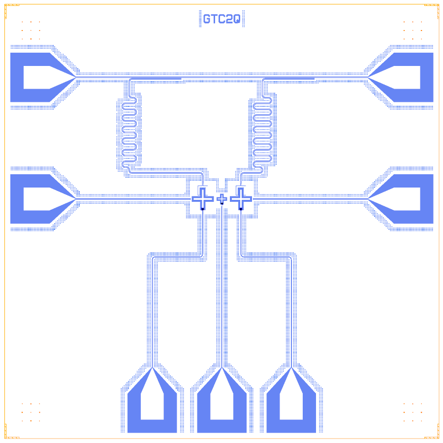
This notebook lays out the tunable-coupler scheme on a chip: three crosses in a row with trilayer SQUIDs, hanger readouts on one feedline, and flux lines.
At a glance¶
Notebook |
|
Source |
Arute et al., Nature 574, 505 (2019); Yan et al., PR Applied 10, 054062 (2018); no public layout |
Chip |
7.5 × 7.5 mm Quantcore die, sapphire 650 µm (εr 10.25), CPW 10 / 6 µm |
On the chip |
2 qubits · 1 coupler · 2 λ/4 hangers · 1 feedline · 7 bond pads |
Builds today |
yes (layout built on 2026-11-19 in 9 s) |
How the notebook builds it¶
Each Design segment is one cell with a picture of the chip so far (see the notebook template).
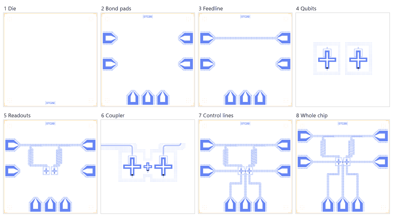
Die. The empty 7.5 mm die with the QCT frame and the device ID
GTC2Q.Bond pads. Seven pads: two for the feedline, two for XY lines, three for Z lines.
Feedline. A straight 10 / 6 µm line between its pads.
Qubits. Two Xmon crosses with Quantcore trilayer SQUIDs (L_J 6.1 nH).
Readouts. Two λ/4 readouts, each ending in a 900 µm hanger on the feedline.
Coupling. The smaller coupler cross between the qubits and the declared capacitances.
Control lines. The XY lines and the Z lines to the south pads.
Whole chip. Centring in the die, targets, sim groups and the save.
LOM estimates¶
Numbers are from a run of this notebook on 2026-11-19 (Setup, Design, Check and the LOM cells, 87 s): QuCat normal modes with QuTiP dressed values.
group |
qubit |
f_q (GHz) |
α (MHz) |
resonator |
f_r (GHz) |
κ (MHz) |
χ (MHz) |
|---|---|---|---|---|---|---|---|
Q1+R1 |
Q1 |
6.668 |
-236 |
R1 |
4.505 |
0.671 |
-0.177 |
Q2+R2 |
Q2 |
6.668 |
-236 |
R2 |
4.585 |
0.705 |
-0.202 |
L_J,c (nH) |
Φ/Φ0 |
f_c (GHz) |
α_c (MHz) |
f_q1 (GHz) |
f_q2 (GHz) |
2·abs(g̃) (MHz) |
g̃ (MHz) |
g̃ Yan Eq. 5 (MHz) |
ZZ (kHz), q2 detuned |
|---|---|---|---|---|---|---|---|---|---|
6 |
0 |
8.765 |
-424 |
6.567 |
6.577 |
10 |
5.01 |
5.1 |
-200 |
6.25 |
0.09 |
8.581 |
-424 |
6.567 |
6.576 |
8.93 |
4.47 |
4.57 |
-177 |
6.5 |
0.126 |
8.408 |
-423 |
6.567 |
6.575 |
7.7 |
3.85 |
3.98 |
-155 |
6.75 |
0.151 |
8.244 |
-422 |
6.567 |
6.573 |
6.3 |
3.15 |
3.3 |
-133 |
7 |
0.172 |
8.09 |
-421 |
6.567 |
6.572 |
4.7 |
2.35 |
2.53 |
-114 |
7.25 |
0.19 |
7.944 |
-418 |
6.567 |
6.57 |
2.84 |
1.42 |
1.64 |
-97.9 |
7.5 |
0.205 |
7.806 |
-414 |
6.567 |
6.568 |
0.664 |
0.332 |
0.614 |
-89.1 |
7.75 |
0.218 |
7.675 |
-408 |
6.567 |
6.565 |
1.91 |
-0.955 |
-0.596 |
-92 |
8 |
0.23 |
7.551 |
-400 |
6.562 |
6.567 |
5 |
-2.5 |
-2.03 |
-115 |
8.5 |
0.251 |
7.322 |
-367 |
6.554 |
6.567 |
13.5 |
-6.73 |
-5.87 |
-296 |
9 |
0.268 |
7.118 |
-302 |
6.54 |
6.567 |
27.2 |
-13.6 |
-11.7 |
-1030 |
9.25 |
0.275 |
7.027 |
-256 |
6.53 |
6.567 |
37.5 |
-18.8 |
-15.8 |
-2060 |
9.5 |
0.282 |
6.943 |
-207 |
6.515 |
6.567 |
51.7 |
-25.9 |
-20.9 |
-4400 |
9.75 |
0.289 |
6.868 |
-159 |
6.496 |
6.567 |
71.5 |
-35.7 |
-26.9 |
-10300 |
group |
qubit |
f_q (GHz) |
α (MHz) |
resonator |
f_r (GHz) |
κ (MHz) |
χ (MHz) |
|---|---|---|---|---|---|---|---|
cell, coupler off |
Q2 |
6.118 |
-194 |
R1 |
4.505 |
0.671 |
-0.175 |
cell, coupler on |
Q2 |
6.112 |
-190 |
R1 |
4.505 |
0.671 |
-0.164 |
group |
pair |
ZZ (kHz) |
neighbours |
hybridised |
|---|---|---|---|---|
cell, coupler off |
Q1-Q2 |
-82.5 |
yes |
no |
cell, coupler off |
Q2-TC |
-7050 |
yes |
no |
cell, coupler off |
Q1-TC |
-15200 |
yes |
no |
cell, coupler on |
Q1-Q2 |
-1830 |
yes |
no |
cell, coupler on |
Q2-TC |
-27000 |
yes |
no |
cell, coupler on |
Q1-TC |
-111000 |
yes |
no |
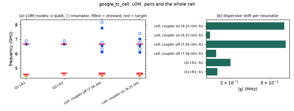
These are lumped-model estimates (component formulas and calibration), not FEM results. The LOM page says how far to trust them.
Build spec¶
The rest of this page is the detailed spec the notebook was built from, with every component, port, route and length.
Sources. Arute et al., “Quantum supremacy using a programmable superconducting processor”, Nature 574, 505
(2019), supplementary information (arXiv:1910.11333): §I “a capacitor-coupled design”, g tunable from +5 MHz to
−40 MHz, “on” coupling ≈ −20 MHz; §II transmon qubits (DC SQUID), 88 couplers, two bump-bonded dies; §III XY + Z
lines per qubit, a Z line per coupler, λ/4 readouts multiplexed on Purcell-filtered lines; Table 2 medians: f_max
6.924 GHz, idle 6.661 GHz, η −208.0 MHz, readout drive 4.618 GHz, κ 0.64 MHz, g_qr 72.3 MHz. Yan et al., “A tunable
coupling scheme for implementing high-fidelity two-qubit gates”, PR Applied 10, 054062 (2018) (arXiv:1803.09813;
local copy build/external/yan2018/): the Q–C–Q circuit of Fig. 2a (C1 70, C2 72, Cc 200, C1c 4, C2c 4.2, C12 0.1 fF,
qubits 4 GHz), the off point of Fig. 2b, Eq. (5) for g̃.
Licence. Papers cited for parameters only; no layout of Sycamore is published (searched GitHub, Qiskit Metal, SQuADDS, KQC and Google Quantum AI repositories; Cirq publishes the device graph only). Layout and code: ours, GPL.
What it is. Two flux-tunable grounded transmons (Xmon-type crosses) and a flux-tunable grounded transmon coupler between them, end-on capacitive coupling of the arm tips; per qubit a λ/4 readout on one feedline, an XY drive line ending open at the outer arm tip and a Z line; a Z line on the coupler.
Chip. PDK standard die 7.5 × 7.5 mm, Quantcore die frame (QCT), device ID GTC2Q; sapphire 650 µm, εr 10.25;
10/6 µm CPW. Junctions: Quantcore trilayer SQUIDs (junction_type="Quantcore Squid"), drawn L_J 6.01 nH at zero
flux (R_n ≈ 40.2 kΩ, C_J 16.8 fF).
Notebook. examples/designs/google/google_tc_cell.ipynb, built from metal:TransmonCrossFL with a Quantcore trilayer substitution, BondPad and OpenToGround.
Components¶
instance |
catalog ref |
key params (µm) |
at (x, y) |
rot |
notes |
|---|---|---|---|---|---|
Q1, Q2 |
metal:TransmonCrossFL |
cross_length 160, cross_width 30, cross_gap 30; claw |
(3750 ∓ 330, 3400) |
0 |
Quantcore Squid, L_J 6.01 nH |
TC |
metal:TransmonCrossFL |
cross_length 70, cross_width 20, cross_gap 20; no claws; flux line |
(3750, 3400) |
0 |
the coupler; Quantcore Squid, L_J 6.01 nH (zero flux) |
XY1_end, XY2_end |
metal:OpenToGround |
width 10, gap 6 |
26 µm beyond the outer pocket edge |
0 / 180 |
XY drive ends (20 µm ground to the pocket) |
FL_in, FL_out, XY1, XY2, Z1, ZC, Z2 |
BondPad |
400 × 450, taper 450 |
edges (see notebook) |
Quantcore pads |
Routes¶
route |
from → to |
type, length |
waypoints / hanger |
notes |
|---|---|---|---|---|
FL |
FL_in.a → FL_out.a |
cpw, 5200 µm |
straight at y = 5500 |
feedline |
R1, R2 |
Q.readout → FL hanger |
meander 6215 / 6095 µm |
hanger s = 1450 / 3750, length 900, side right, ground_gap 4, short |
λ/4 readouts 4.58 / 4.66 GHz |
XY1_line, XY2_line |
XY pad → XY end |
cpw |
straight |
50 Ω drive lines |
Z1_line, ZC_line, Z2_line |
flux_line → Z pad |
cpw 5/3 → 10/6 |
via y = 2400 |
flux bias (controls) |
LOM node structure¶
Q1 island —(C_QC 2.35 fF)— TC island —(C_QC)— Q2 island, plus Q1 —(C_QQ 0.28 fF)— Q2; each island has a SQUID to
ground; Q claw node → R (λ/4 TLres) → HANGER → FL (50 Ω both ends); XY ends → 50 Ω ports; Z lines → flux_bias
controls. C_QC and C_QQ are d.couple estimates (CPS, end-on; C_QQ screened by the coupler, factor 0.15): the Q3D
job core replaces them.
Targets¶
quantity |
source |
rebuild (LOM) |
|---|---|---|
f_q |
6.661 GHz idle (f_max 6.924) |
6.668 GHz alone; 6.57 GHz with the coupler at its off point |
α |
−208 MHz |
−237 MHz alone; −193 MHz in the full cell |
f_r |
4.618 GHz median |
R1 4.577, R2 4.657 GHz |
κ |
0.64 MHz |
0.68 / 0.72 MHz |
g_qr |
72.3 MHz (χ ≈ −0.58 MHz) |
χ −0.20 / −0.23 MHz (g ≈ 45 MHz: claw limited by the arm length) |
g̃ range |
+5 … −40 MHz, on ≈ −20 MHz |
+5.0 MHz at f_c,max 8.77 GHz, 0 at 7.77 GHz, −18.8 MHz at 7.03 GHz, −35.7 MHz at 6.87 GHz |
static ZZ |
– |
−82 kHz at the off point, −1.8 MHz at the on point (qubits 0.45 GHz apart) |
Simplifications / adaptations¶
Planar single die (Sycamore: qubit die bump-bonded to a wiring die); no Purcell filter.
α larger than Sycamore’s for an isolated qubit: the PDK window R_n ≥ 40 kΩ caps E_J at f_q ≈ 6.7 GHz.
The off point and g̃ range follow from the capacitances of cell 1 (C_QQ sets the off point): FEM must confirm.