12-qubit flux processor (Litho)
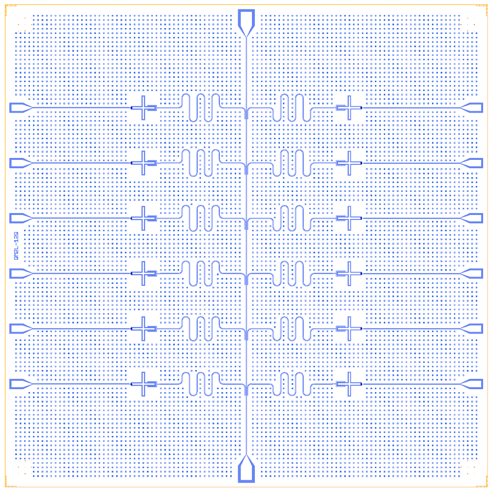
Twelve flux-tunable Xmons in two columns of six, one each side of a vertical feedline. Each has a λ/4 readout (6.05 to 6.82 GHz in 70 MHz steps) and a flux line that runs out to a side pad. The layout is from Qiskit-Metal-to-Litho (CC BY 4.0), rebuilt on the Quantcore PDK with a trilayer SQUID per qubit.
This notebook is an example of a larger chip: twelve readouts and twelve flux lines, with the LOM reading the flux lines as bias lines.
At a glance
Notebook |
|
Source |
Qiskit-Metal-to-Litho |
Chip |
11 × 11 mm Quantcore die (the source’s chip size), feedline 11.7 / 5.1 µm |
On the chip |
14 pads · 1 feedline · 12 flux-tunable Xmons · 12 λ/4 hanger readouts · 12 flux lines |
Builds today |
yes (layout built on 2026-11-19 in 10 s) |
How the notebook builds it
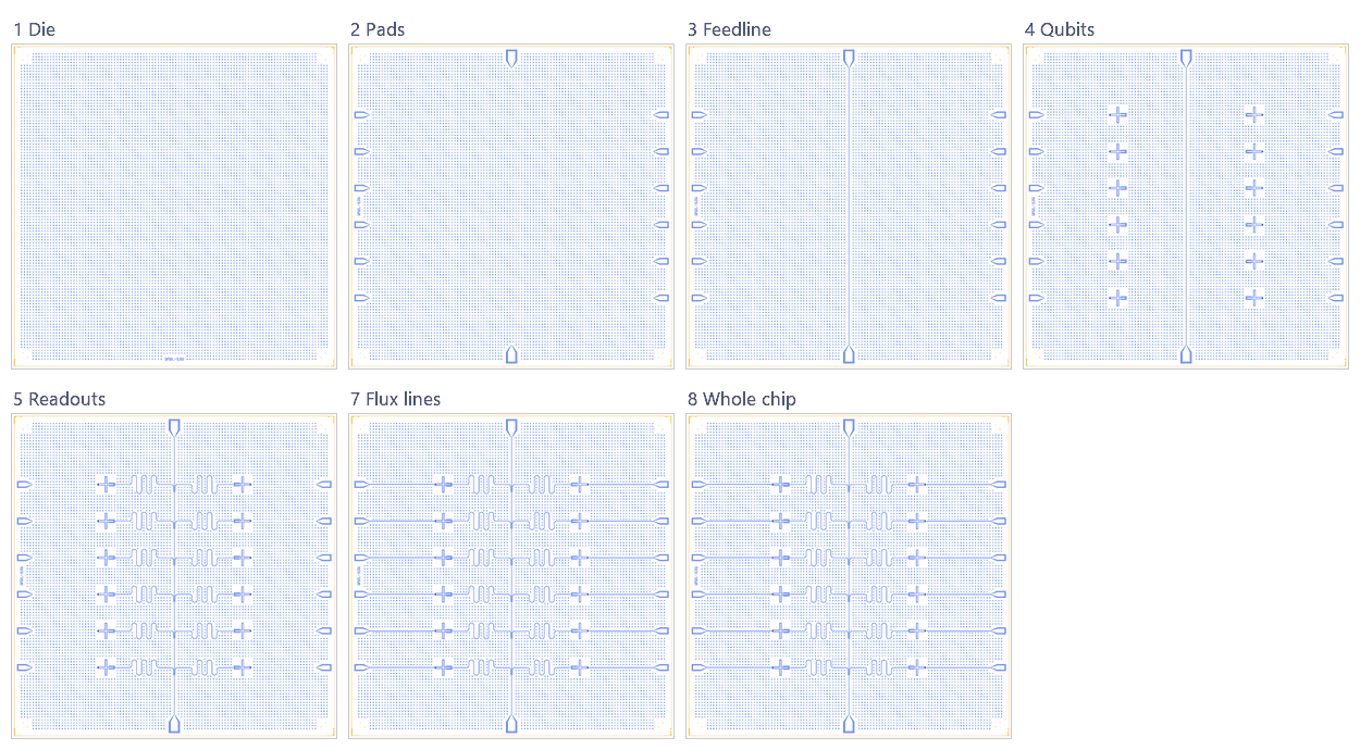
Die. The 11 × 11 mm die with the frame and the device ID
QM2L-12Q.Bond pads. Two launch pads and twelve flux pads, on the 100 µm pad rule.
Feedline. A straight line between the launch pads.
Qubits. Twelve Xmons with trilayer SQUIDs.
Readouts. Twelve λ/4 hangers, one per qubit.
Coupling. None: a readout and flux test processor.
Flux lines. Twelve lines, each to its side pad.
Whole chip. Targets, one sim group per qubit, centring, save.
LOM estimates
Numbers are from the .v1 notebook’s saved output (the 12-qubit chip was not re-run for the docs): each qubit is solved with its readout and the shared feedline, at zero flux. The source states no qubit frequency; the drawn 15.31 nH SQUID puts every qubit at the same 3.258 GHz, below the PDK band of 4 to 8 GHz.
qubit |
f_q (GHz) |
α (MHz) |
resonator |
f_r (GHz) |
κ (MHz) |
χ (MHz) |
|---|---|---|---|---|---|---|
Q01_L |
3.258 |
-150 |
R_Q01_L |
5.742 |
0.0657 |
-0.12 |
Q01_R |
3.258 |
-150 |
R_Q01_R |
5.802 |
0.0677 |
-0.117 |
Q02_L |
3.258 |
-150 |
R_Q02_L |
5.863 |
0.0698 |
-0.115 |
Q02_R |
3.258 |
-150 |
R_Q02_R |
5.923 |
0.0718 |
-0.113 |
Q03_L |
3.258 |
-150 |
R_Q03_L |
5.982 |
0.074 |
-0.112 |
Q03_R |
3.258 |
-150 |
R_Q03_R |
6.042 |
0.0761 |
-0.11 |
Q04_L |
3.258 |
-150 |
R_Q04_L |
6.102 |
0.0783 |
-0.108 |
Q04_R |
3.258 |
-150 |
R_Q04_R |
6.161 |
0.0805 |
-0.107 |
Q05_L |
3.258 |
-150 |
R_Q05_L |
6.221 |
0.0828 |
-0.105 |
Q05_R |
3.258 |
-150 |
R_Q05_R |
6.28 |
0.0851 |
-0.104 |
Q06_L |
3.258 |
-150 |
R_Q06_L |
6.34 |
0.0874 |
-0.103 |
Q06_R |
3.258 |
-150 |
R_Q06_R |
6.399 |
0.0898 |
-0.101 |
These are lumped-model estimates (component formulas and calibration), not FEM results. The LOM page says how far to trust them.
Build spec
The rest of this page is the detailed spec the notebook was built from, with every component, port, route and length.
Source: OJB-Quantum/Qiskit-Metal-to-Litho,
12_Qubit_Flux_Tunable_Processor_in_Colab.ipynb (O. J. Benally, 2026). Output GDS GDS Files/twelve_qubit_flux_processor.gds
(not downloaded). Licence CC BY 4.0 (LICENSE = Attribution 4.0 International; the notebook says “Open Access
(CC-BY-4.0)”), verified. Read on 2026-11-02: notebook constants only, not run.
What it is: 12 flux-tunable Xmons (TransmonCrossFL) in two columns of 6, one each side of a straight vertical
feedline. Each has a λ/4 meander readout, frequency-multiplexed 6.05–6.82 GHz in 70 MHz steps, and a flux line fanned
out to side pads. Quantum Metal draws the qubits and pads; PHIDL smooths the feedline and readout centrelines.
Frame: chip 11 × 11 mm centred. Box (0, 0, 11000, 11000), Designer = source + (5500, 5500). Feedline CPW
11.7/5.1 µm; readout 10/6 µm (fillet 85); flux 6/8 µm tapering to 5/3 µm. Layers: 3 = metal, 5 = flux trace, 9 = junction.
The chip needs Xmon with flux_port, BondPad and hangers. The repository also holds other designs (see bottom).
Components
instance |
catalog ref |
key params (units) |
at (x, y) Designer |
rot |
notes |
|---|---|---|---|---|---|
Qnn_L (n = 1…6) |
|
cross tip-to-tip 520 (Metal cross_length 260), arm_width 35, gap 20. One claw toward the feedline: claw_length 190, width 10, gap 6, ground spacing 5 |
x 3150, y 8650 / 7390 / 6130 / 4870 / 3610 / 2350 |
claw faces +x |
Metal orientation −90; source x −2350, rows y 3150 … −3150 (pitch 1260) |
Qnn_R |
same |
same |
x 7850, same rows |
claw faces −x |
orientation 90 |
P_TOP / P_BOT |
|
(5500, 10200) / (5500, 800) |
180 / 0 |
launch pads at y ±4700 |
|
F_L1…6 / F_R1…6 |
|
x 650 (left) / 10350 (right), one per qubit |
270 / 90 |
flux pads with edge x ±4850 |
Junction: L_J 15.904 nH for all qubits (the SQuADDS tutorial-5 value), so
junction={"Lj_nH": 15.9, "Cj_fF": 2} (Cj assumed). The SQUID is flux-tunable.
Routes
route |
from → to |
type, length |
hanger / waypoints |
notes |
|---|---|---|---|---|
FL |
P_TOP.a → P_BOT.a |
cpw 11.7/5.1, fillet 70 |
straight x 5500, y 9700 → 1300 |
travel −y, so left = +x (east column) |
R_k (12) |
Qk.claw → FL.hanger |
meander L_k = v/(4 f_k), v = 1.20e8 m/s: 6.05 → 4959, 6.12 → 4902, 6.19 → 4847, 6.26 → 4792, 6.33 → 4739, 6.40 → 4688, 6.47 → 4637, 6.54 → 4587, 6.61 → 4539, 6.68 → 4491, 6.75 → 4444, 6.82 → 4399 µm |
coupling section 260 µm, 18 µm from the feedline (3 “teeth”; exact geometry is in the notebook’s manual route code). s at each qubit row (s = 9700 − y_row), side right (west) / left (east) |
meander amplitude solved per resonator (120–360 µm), leads 250 µm |
FLX_k (12) |
Qk.flux → F_k.a |
cpw 6/8 → 5/3 (taper 95 µm), fillet 55 |
escape 360 µm outward, then to the side pad at its row |
Frequency assignment: 12 targets in site order (Q01_L, Q01_R, Q02_L, …), not checked against the rendered GDS.
Launchers, pads, test structures, markers, labels
2 feedline pads + 12 flux pads. No fill in this notebook (the 6-Xmon notebook adds antidots).
LOM node structure
12 grounded Xmon islands (SQUID, flux-tunable through FLX_k). Each claw gives C_g to R_k (λ/4), which gives κ to FL (two 50 Ω ports). There are no qubit–qubit couplers (readout and flux test processor).
Targets
Readout f_k 6.05–6.82 GHz (70 MHz spacing). The first-pass λ/4 model uses v_ph = 1.2e8 m/s. Qubit frequency is not stated.
Simplifications for a first rebuild
Use our standard hanger (ground_gap ≈ 18 − 6 − 5.1 ≈ 7 µm, assumed meaning of the 18 µm gap) and skip the 3-teeth coupler. Flux lines are straight escapes plus one bend to the side pads.
Other repo content (reference only):
6_Xmon_Layout…(spec qm2litho_6xmon), a 400-transmon 20 mm EBL array (GDS Files/400Q-20MM_*.gds,Python Code_BEAMER/400_Qubit_*.py; ground contacts deliberately omitted),Full Chip Ex-001.GDS,4 Qubit Demo.gds,Single Meander CPW Resonator Chip.gds,KI-TWPA_Example.gds. These are GDS/DXF only and were not downloaded.
Build
The notebook uses metal:TransmonCrossFL (flux T-line options from the source), BondPad launch/flux pads with the source sizes, hangers 260 µm with 7 µm ground strip, flux lines straight at 6/8 µm.