100-qubit grid (tutorial 2.22)
A 10 × 10 grid of pocket transmons on a brick lattice (3 mm pitch, odd columns shifted up by 1.5 mm), joined by 176 meandered buses of four slightly different lengths so no qubit sees two equal buses. There are no launchpads, readouts or control lines, and the tutorial calls it “just an example for how to make a design algorithmically”. It is the Qiskit Metal tutorial 2.22 (Apache-2.0, © Qiskit Metal contributors). The Quantcore rebuild is distributed under GPL-3.0.
Build this one to see a large regular array generated by two loops, and how the notebook keeps every bus on Metal’s own corner points. It is the biggest chip in this group (33 mm square) and takes a couple of minutes.
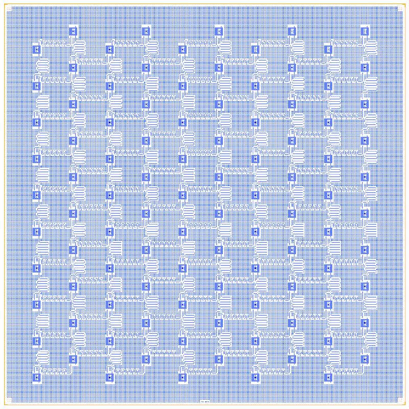
At a glance
Notebook |
|
Source |
Qiskit Metal |
Chip |
33 × 33 mm (the source’s size, far larger than the 7.5 mm Quantcore die) |
On the chip |
100 pocket transmons · 90 upward buses (7.0 / 7.5 mm) · 86 sideways buses (6.0 / 6.5 mm) |
Builds today |
yes (layout built on 2026-11-19 in 136 s) |
How the notebook builds it
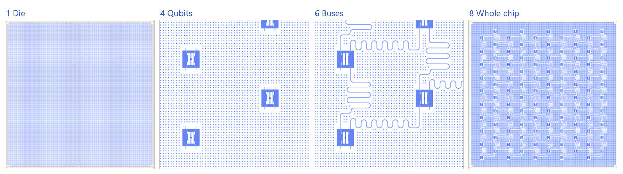
Die. An empty 33 mm square with the QCT frame.
Bond pads. None: the tutorial has no launchpads.
Readout line. None.
Qubits. One hundred Metal pocket transmons with Quantcore junctions (the picture zooms on a corner of the grid).
Readout resonators. None: the free pads on the grid edges stay open.
Coupling. The 176 buses, each a fixed-length route on Metal’s corner points (the picture zooms on a few of them).
Control lines. None.
Whole chip. Sim groups for the FEM jobs (one qubit, and one coupled pair), the content centred in the die, the design saved.
LOM estimates
Numbers are from the .v1 notebook’s saved output (the 100-qubit grid was not re-run for these docs). The LOM cannot solve 100 qubits and 176 buses at once, so the notebook solves the corner qubit Q_0_0 alone, then Q_0_0 with each of two neighbours and the bus between them (a ZZ of 130 kHz for the Q_0_0-Q_0_1 pair; the Q_0_0-Q_1_0 pair hybridises, so no ZZ is given).
group |
qubit |
f_q (GHz) |
α (MHz) |
resonator |
f_r (GHz) |
κ (MHz) |
χ (MHz) |
|---|---|---|---|---|---|---|---|
Q_0_0 |
Q_0_0 |
6.929 |
-295 |
– |
– |
– |
– |
group |
qubit |
f_q (GHz) |
α (MHz) |
resonator |
f_r (GHz) |
κ (MHz) |
χ (MHz) |
|---|---|---|---|---|---|---|---|
Q_0_0+CU_0_0+Q_0_1 |
Q_0_1 |
6.897 |
-287 |
CU_0_0 |
8.355 |
0 |
-2.2 |
Q_0_0 |
6.908 |
-294 |
– |
– |
– |
– |
|
Q_0_0+CS_0_0+Q_1_0 |
Q_1_0 |
6.875 |
10 |
CS_0_0 |
9.511 |
0 |
-2.08 |
Q_0_0 |
6.884 |
-9.53 |
– |
– |
– |
– |
group |
pair |
ZZ (kHz) |
neighbours |
hybridised |
|---|---|---|---|---|
Q_0_0+CU_0_0+Q_0_1 |
Q_0_0-Q_0_1 |
130 |
yes |
no |
Q_0_0+CS_0_0+Q_1_0 |
Q_0_0-Q_1_0 |
– |
yes |
yes |
These are lumped-model estimates from component formulas and calibration, not FEM results. The LOM page says how far to trust them.
Build spec
The rest of this page is the detailed spec the notebook was built from: every component, port, route and length.
The
metal:references in this spec build as written, through themetal:wrapper (ports are the Metal pin names, parameters the Metal options). The Quantcore and KQC substitutions are optional.metal:TransmonPocketbuilds the full topology (give it 4connection_pads; ports appear only for the pads you define), and the Xmon variant is a fallback.
The notebook
examples/designs/metal/tut222_100q_grid.ipynbbuilds the full 4-link topology withmetal:TransmonPocketand Metal’s own RouteMeander corner points.
Source: Quantum Metal docs/tut/2-From-components-to-chip/2.22-Design-100-qubits-programmatically.ipynb. Licence
Apache-2.0.
The chip is an N_x × N_y = 10 × 10 grid of TransmonPocket qubits on a staggered (brick) lattice, joined by λ/2 bus
meanders to the qubit above and to the up-right neighbour. The notebook says it is “not a practical design given the
lack of readouts or control lines”; it is an example of algorithmic layout.
Chip size_x = (N_x + 1)·3 mm = 33 mm and size_y = (N_y + 1)·3 = 33 mm, centred at ((N_x − 1)·1.5, (N_y − 0.5)·1.5) =
(13.5, 14.25) mm. The chip spans x −3…30 mm and y −2.25…30.75 mm, so Designer = Metal + (3000, 2250).
CPW 10/6 µm, fillet 99 µm.
An interior qubit has 4 links (2 north, 2 south), but Xmon and KQC Swissmon have only 3 couplers, so the full
topology needs metal:TransmonPocket. A reduced Xmon variant is described under Simplifications.
Components (generator)
with d.batch():
    for x in range(10):
        for y in range(10):
            at = (x * 3000 + 3000, y * 3000 + (x % 2) * 1500 + 2250)  # odd columns shifted up 1500 µm
            d.add(f"Q_{x}_{y}", "metal:TransmonPocket", at=at, rot=-90, connection_pads=PADS)
Metal options (all qubits): TransmonPocket defaults (pads 455 × 90, gap 30, pocket 650 × 650), orientation −90.
PADS = B0 (loc_W −1, loc_H −1, pad_width 75), B1 (−1, +1, 120), B2 (+1, −1, 120), B3 (+1, +1, 90). The source
typo loc_w on B3 is harmless because loc_W defaults to +1. After the −90° rotation the pins are, relative to the
qubit, B0 (−195, +425) N, B1 (+195, +425) N, B2 (−195, −425) S and B3 (+195, −425) S.
Routes (generator)
family |
condition |
from → to |
meander length (µm) |
leads / asym |
count |
|---|---|---|---|---|---|
CU_x_y (“up”) |
y < N_y − 1 |
Q_x_y.B0 → Q_x_(y+1).B3 |
7000 + (y % 2)·500 |
start 500, end 250, asym −700 |
10 × 9 = 90 |
CS_x_y (“side”) |
x < N_x − 1 and not (x odd and y = N_y − 1) |
Q_x_y.B1 → Q_(x+1)_(y + x%2).B2 |
6000 + (y % 2)·500 |
start 300, end 250, asym −200 |
9 × 10 − 4 = 86 |
The vertical neighbour is 3000 µm up. Because the odd columns are offset, the side neighbour is always (+3000, +1500) up-right. The total is 176 bus resonators, alternating in length so no qubit sees two equal-frequency buses.
Launchers, pads, test structures, markers, labels
None.
LOM node structure
100 transmon islands. An interior qubit couples to 4 λ/2 buses (CU in/out, CS in/out); edge and corner qubits couple
to fewer. There are no ports. This is a stress test for d.lom() scaling: 100 qubits and 176 resonators.
Targets (if stated)
LOM run on Q_0_0 only, with all four pads open: Lj 12.31 nH, Cj 2 fF, freq_readout 6.6 GHz, freq_bus [6.0, 6.2, 6.4] GHz.
Simplifications for a first rebuild
Reduced variant (Xmon, CS links only):
Xmon(claws=["w","e"])at rot 0 on the same staggered grid, with CS_x_y = Q_x_y.claw_e → Q_(x+1)_(y+x%2).claw_w (86 buses). Each column-to-column staircase becomes a chain. This keeps the generator, stagger and frequency alternation but drops the vertical CU links.Build N = 3 × 3 first with the same loops, then N = 10. Wrap the loops in
with d.batch():(276 changes, one rebuild).Full topology: use
metal:TransmonPocket, whose ports are B0–B3.
Quantcore PDK rebuild
The notebook is a Quantcore PDK rebuild of the source, not a replica: the netlist, LOM and imported components are kept, and the process is Quantcore’s.
Notebook: examples/designs/metal/tut222_100q_grid.ipynb.
Chip: the Quantcore die frame (L dicing markers 1000/0, 3 × 3 alignment grids 1001/0, chip boundary 100/0, device ID where an edge is free; any brand text is QCT), drawn on the source’s 33 × 33 mm chip (the design does not fit the 7.5 mm die); no KQC chip frame.
Stack: sapphire 650 µm, εr 10.25 (the PDK default stack, used by the LOM estimates and every FEM export); Metal’s
DesignPlanardefault is silicon (εr 11.45, 750 µm), so the LOM capacitances, resonator frequencies and FEM jobs here are for sapphire rather than the source’s substrate.Junctions: Quantcore Nb/AlOx/Nb trilayer junctions (
junction_typefromlayouts.registry.trilayer_junction): fingers on 2/0 + 4/0, spacer 50/0 with the 51–53/0 gradient, sized on the PDK junction rule (Nb Δ = 1.4 meV, I_c·R_n = πΔ/2e, R_n·A 13.5 kΩ·µm² and C_J 50 fF/µm² assumed); all 100 qubits get the PDK nominal junction, 0.5 × 0.6 µm fingers → R_n = 45 kΩ, L_J = 6.73 nH, C_J = 15 fF (in the 40–50 kΩ window), in place of the tutorial’s LOM value 12.31 nH + 2 fF (a value, not a frequency target). Expected f_q ≈ 6.9 GHz (an estimate), below the 8.5–9.7 GHz λ/2 buses. All qubits stay identical.Kept: the topology and every Metal component with the source’s options (through the
metal:wrapper), positions and orientations, every route’s end pins and total length, the sim groups (the tutorial’s two generator loops, Metal’s own meander corner points).