Your own components
The Quantcore library has 143 components, but a chip often needs a shape that is not among them. This series covers
adding your own: a qubit with a custom island shape, a spiral capacitor, a tunable resonator, and a shape you
drew by hand. A new component works like a library cell: you place it with Designer.add, route to its pins, run the
DRC and get it into the LOM. Read the next section for what a component is, then pick the example closest to what you need.
What a component is
A component has four parts. Placement, routing, DRC, the dashboard and the fab export read them.
Part |
What it is |
In the code |
|---|---|---|
Geometry |
The shapes the cell draws, as a negative mask: it draws what is etched, on |
|
Pins |
Named connection points: a position and a direction pointing out of the component |
|
Junction |
Where a qubit’s Josephson junction sits. The Quantcore trilayer junction (PDK junction rule) is drawn across a gap |
|
LOM model |
The lumped circuit of the component: nodes, capacitances, the junction, which pin is which node |
|
The existing example examples/custom_component/pad_gap_capacitor.py has the first two and a small LOM model. The
series adds a junction and bigger LOM models, and a helper that builds a component from drawn polygons.
The four examples
Page |
Component |
What it shows |
Picture |
|---|---|---|---|
|
A qubit class written by hand: shape from parameters, pins, junction, LOM fragment |
|
|
A spiral or twisted coaxial capacitor |
A passive component with two pins and a capacitance model |
see the page |
|
A λ/4 resonator with a SQUID array at its shorted end |
A resonator with a junction tree and a flux pin |
see the page |
|
|
Polygons (drawn in Python or in KLayout) + pins + a junction location become a component |
|
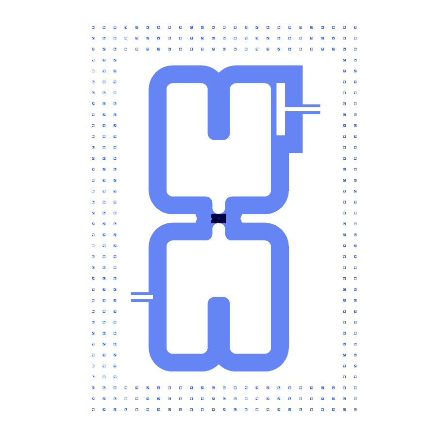
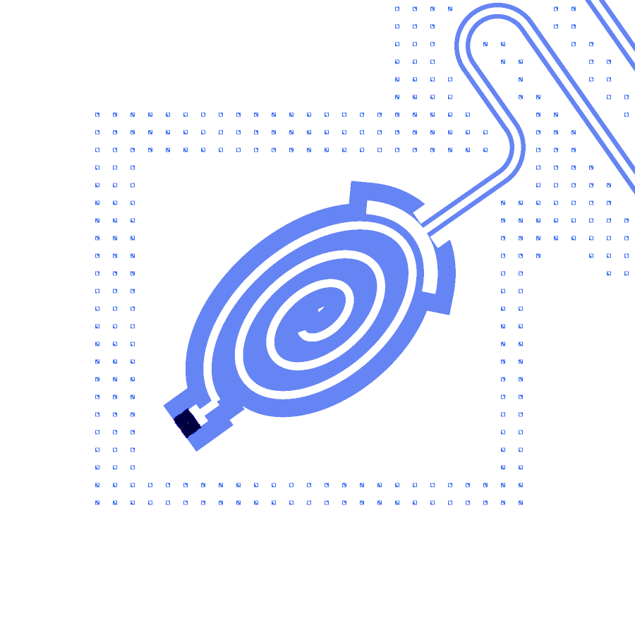
The code is in examples/custom_component/. The notebook custom_qubits.ipynb places the two qubits on a small chip
with a readout, builds them, runs the DRC and the LOM (no FEM). custom_passives.ipynb does the same for the two
passive components.
Make your own, step by step
Pick the closest example in the table and copy its file. Name the class after the shape.
Write the parameters (
Param(pdt.TypeDouble, "text", default, unit="μm")) for every number the shape needs. The panel,design.jsonand the LOM read them.Write
build(). Draw the metal as regions, etch a clearance around it, add the protection region, add the pins (position and outward direction). For a qubit, callplace_trilayeracross the junction gap.Set
qcc_category("qubit","capacitor","resonator", …). The panel’s class filter, the DRC and the fab export read it.Check the picture. Build the cell alone on a die and look at it (
snapshot). Check that every pin leaves the component along its direction.Add the LOM model. Give each conductor a node, each pin a node (
port_nodes), and each branch a value from a formula inquantcore_circuits.lom.estimates. Mark honest values as"rough". A Q3D C-matrix of the cell replaces them later by net name.Register the class. A class inside
src/quantcore_circuits/layouts/is registered automatically. A class in your own folder registers itself withquantcore_circuits.layouts.register_pcell_classes([MyClass])and is referred to by its dotted path,"my_module.MyClass".Place it on a chip with a readout, route to the pins, run
d.drc(), and run the LOM.
Note
A component that lives outside the package is found by its dotted path only while its folder is on sys.path. To
make it a permanent library cell (plugin panel, qcc components, design.json anywhere), copy the file into
src/quantcore_circuits/layouts/qubits/ (or others/) and restart KLayout. See Components.
Where to read more
Components: the libraries and how pins connect.
LOM: what the lumped model does and how far to trust it.
Routing and DRC: what the DRC checks on pins and routes.
PDK: the junction rule and the clearances.